
CENTER FOR
COMPOSITES MANUFACTURING
FABRICATION GUIDE
JUNE 2002
FTA REPORT NUMBER FTA-AL-26-7001.2
FABRICATION GUIDE FOR
COMPRESSION MOLDING OF LONG FIBER THERMOPLASTIC COMPOSITES
CENTER FOR
COMPOSITES MANUFACTURING
FABRICATION GUIDE
JUNE 2002
FTA REPORT NUMBER FTA-AL-26-7001.2
FABRICATION GUIDE FOR
COMPRESSION MOLDING OF LONG FIBER THERMOPLASTIC COMPOSITES
REPORT DOCUMENTATION PAGE |
Form Approved OMB No. 0704-0188 |
||||||||
|
Public reporting burden for this collection of information is estimated to average 1 hour per response, including the time for reviewing instructions, searching existing data sources, gathering and maintaining the data needed, and completing and reviewing this collection of information. Send comments regarding this burden estimate or any other aspect of this collection of information, including suggestions for reducing this burden to Department of Defense, Washington Headquarters Services, Directorate for Information Operations and Reports (0704-0188), 1215 Jefferson Davis Highway, Suite 1204, Arlington, VA 22202-4302. Respondents should be aware that notwithstanding any other provision of law, no person shall be subject to any penalty for failing to comply with a collection of information if it does not display a currently valid OMB control number. PLEASE DO NOT RETURN YOUR FORM TO THE ABOVE ADDRESS. |
|||||||||
|
1. REPORT DATE (DD-MM-YYYY) 6-6-2002 |
2. REPORT TYPE Final |
3. DATES COVERED (From - To) From 3-15-01 to 5-31-02 |
|||||||
|
4.
TITLE AND SUBTITLE Center for Composites Manufacturing |
5a.
CONTRACT NUMBER |
||||||||
|
Fabrication Guide |
5b.
GRANT NUMBER FTA-AL-26-7001 |
||||||||
|
|
5c.
PROGRAM ELEMENT NUMBER |
||||||||
|
6.
AUTHOR (S) Klaus F. Gleich and Thomas E. Jackson |
5d.
PROJECT NUMBER |
||||||||
|
|
5e.
TASK NUMBER |
||||||||
|
|
5f. WORK UNIT NUMBER |
||||||||
|
7.
PERFORMING ORGANIZATION NAME(S) AND ADDRESS(ES) AND ADDRESS(ES) |
8.
PERFORMING ORGANIZATION REPORT NUMBER |
||||||||
|
Southern Research Institute 757 Tom Martin Dr. Birmingham, Al 35211 |
|
|
|||||||
|
9. SPONSORING / MONITORING AGENCY NAME(S) AND ADDRESS(ES) |
10. SPONSOR/MONITOR’S ACRONYM(S) |
||||||||
|
|
|
|
|||||||
|
|
|
|
|||||||
|
|
|
11. SPONSOR/MONITOR’S REPORT |
|||||||
|
|
|
NUMBER(S) |
|||||||
|
|
|
FTA-AL-26-7001.2 |
|||||||
|
12.
DISTRIBUTION / AVAILABILITY STATEMENT |
|||||||||
|
13.
SUPPLEMENTARY NOTES |
|||||||||
|
14. ABSTRACT This report describes thermoplastic composite materials and processes and demonstrates fabrication methods for molding these materials into passenger seating components or other large components for use in buses and other mass transit applications. The primary goal of this work was to demonstrate that these technologies could provide lower cost, lighter weight, improved performance structures for mass transit applications. This fabrication guide was written to outline the basic requirements involved in design and fabrication of large long-fiber thermoplastic composite parts by compression molding. |
|||||||||
|
15. SUBJECT TERMS Long fiber thermoplastic composite compression mold simulation bus seat manufacture cost weight reduction |
|||||||||
|
16.
SECURITY CLASSIFICATION OF: |
17.
LIMITATION OF
ABSTRACT |
18.
NUMBER OF PAGES |
19a.
NAME OF RESPONSIBLE PERSON |
||||||
|
a.
REPORT |
b.
ABSTRACT |
c.
THIS PAGE |
|
|
19b.
TELEPHONE NUMBER (include
area code) |
||||
|
|
Standard Form 298 (Rev. 8-98) Prescribed by ANSI Std. Z39.18 |
||||||||
CENTER FOR
COMPOSITES MANUFACTURING
FABRICATION GUIDE
JUNE 2002
Prepared by
Klaus F. Gleich and Thomas E.
Jackson
Southern Research Institute
757 Tom Martin Drive
Birmingham, AL 35211
Prepared for
Federal Transit Administration
U.S. Department of Transportation
Washington, DC 20590
Available from
National Technical Information
Service (NTIS)
5285 Port Royal Road
Springfield, Virginia 22161
703-605-6000
703-605-6900 Fax
Email
[orders@ntis.fedworld.gov]
Report Number
FTA-AL-26-7001.2
Table of Contents
Page
Table of Contents............................................................................................................... 2
List of Figures..................................................................................................................... 4
List of Tables...................................................................................................................... 4
Forward/Notice................................................................................................................... 5
Acknowledgement............................................................................................................... 6
Executive Summary............................................................................................................ 7
1 Introduction..................................................................................................................... 8
2 Objectives....................................................................................................................... 9
3 General Description of LFT Compression Molding................................................... 10
3.1 Processing Guidelines................................................................................... 11
3.1.1 LFT-Compression Molding............................................................ 11
3.1.2 Guidelines for Equipment............................................................... 13
3.1.3 Plastication...................................................................................... 13
3.1.4 Vented Barrel Feature................................................................... 14
3.2 Material Feeding and Dosing....................................................................... 14
3.3 Special Requirements for Processing of Production Scrap......................... 14
4 Press Requirements..................................................................................................... 16
5 Guidelines for Material Handling and Processing...................................................... 17
5.1 Material Preparation..................................................................................... 17
5.2 Temperature and Screw Speed..................................................................... 17
5.3
Back pressure................................................................................................ 18
5.4
Plasticate Time in Air.................................................................................... 18
Table of Contents
Page
5.5 Clamping Tonnage and Compression Speed................................................ 19
5.6 Handling of the Plasticated Material............................................................ 20
5.7 Flat Sheet Die versus Round Die for Charge Formation............................ 20
5.8 Mold Temperature........................................................................................ 20
5.9 Placement of Charges(s)............................................................................... 20
5.10 Typical Cycle Times.................................................................................... 21
5.11 Special Guidelines for Compression Molding with Local Inserts............. 21
6 Guidelines for Material Handling and Processing...................................................... 22
7 Tooling Guidelines........................................................................................................ 24
Glossary
of Abbreviations and Acronyms....................................................................... 25
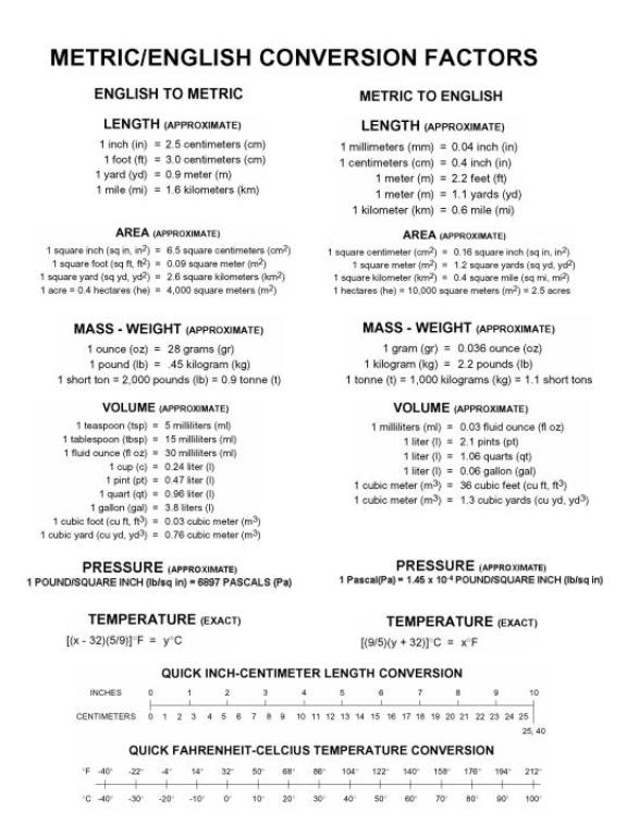
Metric Chart..................................................................................................................... 26
List of Figures
Page
3-1 The DRIFT Impregnation Process................................................................... 10
3.1.1-1... Compression Molding Line for LFT (Source: C.A. Lawton)........................... 11
3.1.1-2 Working Principle of a Plasticator.................................................................... 12
6-1 Design of Wall Thickness Changes in a Component....................................... 22
6-2 Typical Rib Design for LFT Compression Molding........................................ 23
List of Tables
Page
3-1 Properties
of Several Thermoplastic Composites Produced........................... 10
3.1.2-1
Typical Technical
Requirements for Equipment to Process
LFT Pellets in Compression Molding............................................................... 13
5.2-1
Typical Processing
Temperatures for LFT Compression Molding................. 18
5.4-1
Heat Stabilizers
and UV Stabilizers for Polypropylene and
Nylon 6............................................................................................................... 19
6-1 Shrinkage
Data for some LFT Material.......................................................... 23
Foreword
This fabrication guide describes steps require to apply the technology of long-fiber thermoplastic composites in transit bus applications for the Department of Transportation and the Federal Transit Administration. The goals of improved safety, reduced weight, and lower cost are very important to the transportation industry. This report describes the design guidelines and fabrication methods related to compression-molded long-fiber thermoplastic composite transit bus components.
This document is disseminated under the sponsorship of the United States Department of Transportation in the interest of information exchange. The United States Government assumes no liability for its contents or use thereof.
The United States Government does not endorse manufacturers or products. Trade names appear in the document only because they are essential to the content of the report.
Acknowledgment
The authors wish to express their appreciation to the Federal Transit Administration for the support of this work. We thank the C.A. Lawton Company for the use of their plastication equipment and North American Bus Industries for their guidance in component selection and design guidelines. We acknowledge the following for their contributions to the technical effort of this project: from Southern Research Institute, George Husman, Tim Hartness, Patric Moriarty, Mike Dyksterhouse, and Andy Grabany; from The University of Alabama at Birmingham, Uday Vaidya, Greg Janowski, Krish Chawla, Chad Ulven, Shane Bartus, Brian Pillas, and Jianguang Zhang; and from Polycomp, Joel Dyksterhouse. We acknowledge and thank Lisa White for her assistance with the preparation of this report.
Executive Summary
The Center for Composites Manufacturing Fabrication Guide outlines part design, processes requirements, material selection, tooling, and equipment specifications related to the manufacture of large parts by compression molding.
This guide describes the process by which long fiber thermoplastic prepreg is formed and also relates these materials to several mechanical properties of unidirectional and randomly oriented composite panels. Descriptions of the critical equipment, plasticator, press, and tooling are given with an emphasis on equipment capabilities and specific performance characteristics. Some discussion of material handling and recycling of scrap is also treated.
There are sections on part design as it relates to the practical manufacture of parts with minimal warpage, minimal porosity, rib specification and shrinkage estimates. These issues are intimately related to the design of the mold tooling itself. Tooling specifications with regard to mold deflection, shear edge design, slides and ejector pin locations are included.
1 Introduction
The Federal Transit Administration (FTA) has encouraged innovative technologies to be implemented in mass transit applications, particularly when improvements in safety, performance, cost, or weight reduction may be realized. The results of efforts made by Southern Research Institute under FTA Project AL-26-7001 were directed to the fabrication long fiber thermoplastic composite bus seats to demonstrate the contribution of several technologies. Primary considerations for this application were weight savings, which would reduce fuel consumption, and cost savings to encourage usage in commercial applications. The choice of bus seats as a thermoplastic composite application goal was the result of consideration of overall weight reduction calculations for several bus components. The primary selection issue was based on the quantity of two-person seats installed on a standard transit bus as well as the potential weight of the individual seat. Other weight and cost reduction efforts could be made on additional components and substructure of transit buses. Some of these opportunities will be addressed in future efforts.
2 Objectives
The intent of this report is to provide general guidance in the design, and fabrication of a large compression-molded long fiber thermoplastic (LFT) composite part for use in a commercial transit bus. The major manufacturing issues will be addressed involved in part design, prototyping, tooling and fabrication.
Long fiber-reinforced thermoplastics can be produced in a wide variety of resin and fiber combinations. The following information is based on the Direct Reinforcement Fabrication Technology (DRIFT) impregnation process (Figure. 3-1). This process permitted in-house production of raw materials using any combination of fibers and polymers that were compatible and practical for the bus seat application or for other large parts.
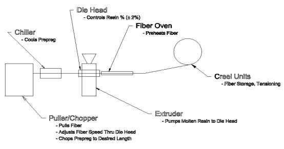
Figure 3-1 The DRIFT Impregnation Process
The DRIFT impregnation process is a hot melt pultrusion process. The fiber is pulled from a creel and heated at or above melt temperature. A single or twin-screw extruder compounds the resin. The heated roving is impregnated in a die with the melted resin by opening the fiber bundles over specially designed spreader surfaces. After calibration to the final fiber content, the LFT material was shaped to tapes or small profiles or cut into pellets of typically 12.7 to 50.8 mm length.
The resulting LFT-materials were converted into unidirectional or compression molded test plaques and tested according to the ASTM test standards. Table 3-1 gives an overview of typical material data from low oriented samples.
|
Material Type |
PE GF40 |
PP GF40 |
PP GF50 |
PP GF60 |
PA GF40 |
|
Density g/cm3 |
1.27 |
1.23 |
1.34 |
1.43 |
1.46 |
|
Tensile Strength
(MPa) |
109 |
84 |
92 |
120 |
180 |
|
Tensile Modulus
(GPa) |
9.6 |
7.6 |
10.3 |
12.1 |
14.8 |
|
Notched Izod (J/m) (Long/Trans) |
1020 / 384 |
561 / 294 |
609 / 278 |
748 / 240 |
972 / 412 |
|
Falling Dart Impact
(kJ) |
2.8 |
2.8 – 3.4 |
3.0 |
3.2 |
3.1 |
Table 3‑1 Properties of Several Thermoplastic Composites Produced
The material data shown can be used as a guideline for design and stress analyses. The resulting properties in a part can vary according to material recipes, processing conditions, fiber orientation and component design. The performance of thermoplastic composites is affected by the specific polymer, fiber characteristics (coupling agents and lubricants), colorants, heat stabilizers, flame-retardants, and ultra-violet light (UV) stabilizers with all other factors being equal. Issues of fiber orientation and component design are intimately related to the performance of a given material and should therefore be carefully studied during the design phase. It is for this reason that component designs made with metals should not be simply converted to long fiber thermoplastic composite designs without study of the fiber orientation effects needed for good performance.
3.1.1 LFT-Compression Molding
Figure 3.1.1-1 shows a typical compression molding line for LFT. The working principle of a reciprocating screw plasticator can be seen in Figure 3.1.1 -2. The LFT is fed into a low shear screw. During transportation along the screw, the LFT is melted, and if necessary, mixed. The moving material is collected in front of the screw by moving the screw backward against a back pressure. After the required charge size is accumulated, the screw stops turning, the charge is extruded through a die and laid on a conveyor belt. The charge is picked up manually or by a robot and placed in a compression tool within a press. The press is closed; the material cools down in the tool and is removed after consolidation.
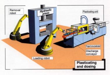
Figure 3.1.1-1 Compression
Molding Line for LFT (Source: C.A. Lawton)
Figure 3.1.1-2 Working Principle of a Plasticator
3.1.2 Guidelines for Equipment
To process LFT-pellets, special equipment is needed. Table 3.1.2-1 gives general recommendations for equipment to process LFT-pellets in compression molding.
|
Minimum |
Recommended[1] |
Maximum |
Comment |
|
Plasticator
|
|
|
|
|
|
Screw diameter |
80 mm |
> 130 mm |
n.a. |
|
|
L/D ratio |
24 |
Approx. 30 |
40 |
L/D ratio over 40 will increase fiber damage and residence time in the plasticator |
|
Screw speed |
n.a. |
8 to 50 rpm |
n.a. |
High torque at low speed is required |
Press
|
|
|
|
|
|
Closing speed |
500 mm/sec |
> 800 mm/sec |
n.a. |
|
|
Compression speed |
25 mm/sec |
40 – 70 mm/sec |
n.a. |
|
|
Deflection |
|
<0.1mm/meter |
|
At full press force |
|
Level control |
|
<0.12mm/meter |
|
At full press force |
|
Pressure Buildup Time |
|
<0.3 sec |
|
|
|
|
|
|
|
|
|
Charge |
|
|
|
|
|
Thickness for flat sheet |
4 mm |
> 7 mm |
50 mm to 70 mm (depends on press) |
A thicker charge may be required for low fiber content |
Table 3.1.2-1 Typical technical requirements for equipment to process LFT-pellets in compression molding
3.1.3 Plastication
Most common means of plastication uses a reciprocating single screw extruder. Composite chip is generally metered into the extruder in a starve-feed mode using a control signal from the extruder. The screw must be designed with a low internal shear to prevent fiber damage. As a result, the barrel heaters must be designed to introduce at least 90% to 100% of the energy needed for melting of the LFT pellets rather than depending upon the shearing action of the screw. The screw and barrel must be protected against abrasion by using hardened surfaces or intrinsically hard materials in both components. The motor and gearbox must be designed to run high torque at low speed because high speed will damage the fiber. A hydraulic screw motor is recommended for this service for the sake of torque, speed and speed control. Also single screw extruders may benefit from having a conveyor belt and an integral cutting knife.
3.1.4 Vented Barrel Feature
Degassing of the melted LFT improves shot size accuracy. A properly located barrel vent and high volume vacuum system for removing gases, such as water vapor, reduces the porosity of the final component and improves surface quality. Therefore, degassing from a vented barrel can be a distinct processing advantage. On the other hand, screws for degassing of polymers are less gentle to the material, and can increase fiber damage. Designing a degassing screw and barrel for LFT requires a significant knowledge of LFT processing. Such screws have limited flexibility of use with different materials; therefore, one screw is generally designed for a very limited selection of LFT-materials. Therefore, different degassing screws will often be needed for different materials.
3.2 Material Feeding and
Dosing
The consistency of plastication process depends very much upon the consistency of the feeding of the LFT-pellets into the extruder. Often LFT-pellets are not free flowing due to the length of the individual pieces; therefore, they tend to bridge in the feeder/hopper unit. Bridging can either cause erratic feeding or halt feeding completely depending upon the severity of the circumstance. Generally, the longer the pellets, the more common feeding blockages occur. Usually vacuum feeder without problems can feed 12.7 mm long pellets and vacuum feeders can also feed pellets up to 25.4 mm as long as the surface and cut-edge quality are sufficiently good. They can also be successfully fed by conveyor belt systems or with large diameter flexible screws. For pellets longer than 25.4 mm, only conveyor belt systems can be recommended. Material hoppers should always avoid sharp edges. These tend to encourage bridging. For consistent feeding, a volumetric vibrational feeder is recommend at the exit of the hopper.
Although flood feeding is possible with long fiber pellets, more consistent feeding and better quality plasticate can be achieved by using starve-feeding units. Volumetric vibrational feeders are recommended for pellets longer than 25.4 mm. If highly filled pellets (e.g., fiber content of 60% or higher) are used, volumetric dosing units for all components (pellets, resin, and other different additives) are necessary. Mixing components close to the throat of the extruder can avoid settling problems associated with batch mixes of powders, long pellets and resin pellets.
3.3 Special Requirements for
Processing of Production Scrap
Economic advantages are often realized by recycling production scrap in a given process. LFT production scrap is usually shredded into large pieces to keep the fiber intact so that they can contribute positively to the mechanical properties of the part being manufactured. As a result of the shredding process, fiber bundles will often stick out of the edges of the scrap. Therefore shredded materials will tend to bridge much more often than standard LFT-pellets. Feeding of scrap material is therefore more difficult. Only vibrational feeders should be used for feeding scrap, and the scrap material should be fed to a hopper only by using conveyor belt systems. Metal detection systems are recommended so that the metal parts can be rejected before damaging the extruder or the tool itself. Recycled scrap materials also have a lower bulk density as a result of the irregular shapes, and even heat transfer may be more difficult requiring a screw heater or material preheating prior to feeding it into the screw.
4
Press Requirements
A high-speed, down-acting press with level control is recommended for compression molding of LFT materials. The closing speed should be at least 800 mm/sec, and the compression speed should be at least 40 mm/sec. The rapid closure and compression minimize the time of the plasticated charge in the tool so that full material compression and forming occur. Though less expensive, slower presses can allow the material to freeze before completely filling the mold cavity. Likewise, though more expensive, a good platen level control is useful to protect the shear edges of the tool, reduce variation of part thickness and obtain consistent material flow in all parts.
Another important press performance factor is the pressure buildup time. During the pressure buildup time, the material can freeze on the tool surface without proper flow. Best results can be achieved with a pressure build up time of less than 0.3 sec. For prediction of the required tonnage of the press, check the processing section.
5 Guidelines for Material Handling and
Processing
5.1
Material Preparation
Any water must be removed from the resin, pellets, additives and plasticator before processing. Water in a plasticator can act violently like an explosive. In most cases, materials based on fiberglass and polyolefins are not as critical with respect to drying. Many other resins, such as Nylon-based LFT, must be dried before use. The use of resins in the presence of water may not only cause violent discharges of material and porosity, but also can lead to critical reductions in the molecular weight of the resin. In any case, the presence of water in the material will severely compromise the quality of the parts produced. Likewise, any residual gas in the melt reduces shot size accuracy and also will contribute to porosity.
The implementation of starve-feeding of the LFT-pellets will reduce fiber damage and gives a more consistent charge. Inconsistent feeding creates a high variation in shot size, and under flood-feeding conditions, may move the extruder screw back without any material being in the charge area.
5.2 Temperature and Screw
Speed
A low plasticator screw speed should be chosen to avoid fiber damage. In most cases, screw speeds between 8 and 25 rpm are adequate for rapid plastication without compromising fiber length. Additives of an abrasive nature may require additional speed reduction to avoid fiber damage.
The barrel temperature profile must correlate to the screw speed as well as the polymer itself. Most of the fiber damage occurs when pellets are only partially melted. Therefore, it is important to get most of the melting done before a high level of shear is applied to the material. Typical processing temperatures are shown in Table 5.2-1. The set point of the heaters may need to be increased to maintain the given temperatures depending on the position of the thermocouples.
|
|
|
Processing Temperatures oC |
Drying |
|||||
|
Resin |
Fiber |
Rear |
Center |
Front |
Die |
Melt |
Time hr |
Temp. oC |
|
|
|
|
|
|
|
|
|
|
|
HDPE |
Glass, Carbon, Aramid |
190 |
200 |
210 |
210 |
210 |
1.52 |
100 |
|
HDPE |
Natural Fiber |
170 |
180 |
190 |
190 |
190 |
3 |
100 |
|
PP |
Glass, Carbon, Aramid |
220 |
235 |
235 |
235 |
235 |
2[2] |
100 |
|
PP |
Natural Fiber |
170 |
180 |
190 |
190 |
190 |
3 |
100 |
|
Nylon 6 |
Glass, Carbon, Aramid |
245 |
260 |
270 |
270 |
270 |
4 |
80 |
Table 5.2-1 Typical Processing Temperatures for LFT Compression Molding
If natural fibers are used for reinforcement, the melt temperature should be as low as possible to avoid decomposition of the fiber.
5.3 Back Pressure
Back pressure exerted on an accumulating plasticator charge is an important factor for processing LFT-pellets. If the back pressure is too high, fiber damage will increase. Low back pressure will encourage porosity in the component, since trapped air cannot leave the charge and will be captured in the middle of the part during the molding process. The presence of air or other gases will also influence shot size accuracy by affecting the bulk density of the material. It is recommended that back pressure on the accumulating charge be between 1 and 2 MPa for most of the materials.
5.4 Plasticate Time in Air
High temperature and the presence of oxygen break the polymer chains. Therefore, the materials are usually stabilized for thermal oxidation and not unnecessarily exposed to oxygen in the air. Time is a key factor to keep the material intact. If during the process cycle, materials are exposed to oxidative conditions, the stabilizing agents may be consumed, and then thermal oxidation of the polymer will take place. This will generally result in a reduction of desired mechanical properties. Common stabilizers and amounts added are found in Table 5.4-1. This is not an exhaustive list, but rather a list based on application experience.
|
Material |
Heat Stabilizer/amount Wgt % of resin |
UV Stabilizer/amount Wgt % of resin |
|
Polypropylene |
Schulman, PAO 3360 /1.5% or CIBA Irganox B225/
1.5% |
CIBA, Tinovin 783
FDL/1% |
|
Nylon 6 |
CIBA, Irganox B1171/1% |
---- |
Table 5.4-1 Heat Stabilizers
and UV Stabilizers for Polypropylene and Nylon 6
The chemical reactions will vary with the different materials. Polyolefins are mainly degraded by the influence of heat and oxygen. Therefore, the time in air after ejection is important. A well-stabilized material can be in air for more than 1 minute without any consequence, but Nylon can be damaged by heat alone or the combination of heat and oxygen. Therefore, both the times in air as well as the residence time in the plasticator are important. The time window between ejection of the plasticated charge and closing the mold is approximately 10 to 15 seconds. Increasing the amount of stabilization additives can increase the handling window but can also negatively influence mechanical properties and add to the basic recurring cost of the part.
5.5 Clamping Tonnage and
Compression Speed
Pressure and speed should be considered together. In order to fill a tool at a lower closing speed, a higher press tonnage is required. Often, it is not possible to fill the mold with low speed and high tonnage because during the closing step, the material is slowly flowing and then freezing on the surface of the tool. We recommend a compression speed at full pressure of about 40 to 70 mm/sec in addition to rapid unloaded closure. The necessary tonnage depends upon the flow distance, the part thickness and geometry, the viscosity of the material as well as tool temperature. Most parts can be fabricated with a specific pressure calculated on the projected part surface of 1 MPa to 1.7 MPa. That means a part of approximately 1 m2 projected surface area with a geometry that is easy to fill can be processed with a 1500 metric ton press. A component with the same surface area but with a complex flow pattern and/or thin wall thickness may need up to a 2500 metric ton press.
After calculating the necessary press tonnage, one must add the tonnage of the leveling system. That is, if a part requires 1500 metric tons and the leveling system is 300 metric tons, then the total tonnage needed from the press is 1800 metric tons.
If the press tonnage is not sufficient, a part can be filled but may have high level of porosity, which will result in poor mechanical properties.
5.6 Handling of the
Plasticated Material
Material handling often depends on the production volume. Manual handling is commonly used for prototyping. Manual handling is more flexible and permits testing different charge patterns without time consuming programming changes. For higher volume production, an automated handling unit is preferred.
It is recommended that the charge be no less than 5 mm in thickness. If one has a very low fiber content material, a higher thickness might be required to avoid distortion during handling. The maximum thickness of the charge (including lofting) should not be equal to or more than the maximum distance required for the pressing speed on the press. In most cases, this will be somewhere between 50 and 70 mm.
5.7 Flat Sheet Die versus
Round Die for Charge Formation
Charge pattern and shapes depend upon the part and material flow requirements. Often, it is easier to work with flat, rectangular cross-section sheets. It can also be advantageous to process a part with a round cross-section charge because the surface area of the round cross-section charge is less and heat loss is reduced. This is a fine point, but could translate into longer useful airtime or could make the difference in filling the mold with the press that is available. Selection of the charge cross-section depends upon the shape of the part and the rate of production of the plasticated charges.
5.8 Mold Temperature
Typical tool temperatures for polypropylene (PP) based LFT are between 30oC and 80oC. Higher tool temperature improves surface quality, but also increases cycle time, and therefore, part cost. It is usually preferred to operate at lower tool temperature for the sake of economics, but the rate of material cooling in the tool also influences the crystallization behavior of the resin. The crystallization characteristics of some resins have profound influences on mechanical and chemical performance. The cooling rate even influences part warpage. Other materials require higher tool temperatures for good material performance. Nylon based material requires a slightly higher tool temperature, approximately 90oC, and polybutylene thermoplastic (PBT)/ polythylcue thermoplastic (PET) based material requires tool temperature in the range of 135 – 150oC.
5.9 Placement of Charge(s)
Charge size, number, and placement always depend on the part and the material. Therefore, no general recommendations can be given. Flow simulation should be used to optimize the charge pattern. The use of a computer simulation program such as CADpressÔ is applicable to LFT composite processing, and therefore should be given serious consideration. If multiple charges are used, the charges should always have overlap to avoid weld lines.
5.10 Typical Cycle Times
Cycle times depend on wall thickness, resin type, geometry, warpage requirements and tooling material. Most of the parts can be produced with a cycle time less than 60 sec in a metal tool. For a PP based LFT and a wall thickness of approximately 2 to 3 mm a cycle time less than 40 sec can be achieved in a metal tool. The determination of cycle times is strongly related to the heat transfer properties of the tool and the material itself. Metal tooling possesses an intrinsically higher thermal conductivity than epoxy tooling; therefore much shorter cycle times are possible. Cost is the tradeoff in selection of tooling materials both with respect to cycle time and durability.
5.11 Special Guidelines for
Compression Molding with Local Inserts
Local inserts of unidirectional LFT or woven LFT can be used to improve mechanical properties in special areas, that is carbon fiber inserts can be strategically placed to increase stiffness in a given part. These inserts must be pre-impregnated. Depending on the part, they can be placed directly in the tool; some must be pre-shaped. The resin type must be the same as used in the basic LFT pellets or must be very compatible to it. If the materials are not compatible, then the insert will only be mechanically connected and will fail at low loading. In order to get good bonding with the basic LFT, the insert surface must be melted during the processing. In some cases, this can be achieved by using only the heat of the plasticated LFT-pellets. In other cases, preheating the insert is required for proper bonding. The fixing of inserts in a tool requires attention to the tool design itself and should be an afterthought. In some cases a three-plate-mold in which the middle plate is a fixing frame for the insert is implemented.
The basic guidelines for LFT-compression molded components are the same as for compression molding of glass mat thermoplastic composite (GMT). Because of superior flow and fiber distribution of LFT materials, ribs can be thinner than using GMT.
The most important guidelines are the following:
· Changes in thickness have to be avoided wherever possible. At least minimize then. During cooling, areas with different thicknesses shrink differently, causing greater porosity in thick areas. Thickness variations also encourage warpage due to different cooling dynamics. If changes in part thickness cannot be avoided, it is best to taper the change gradually over a long distance. Figure 6-1 illustrates this principle. The length of the transition in thickness should be at least 3 times of the change in thickness. Avoid changes in thicknesses that are more than 3 mm.
Figure 6-1 Design of Wall Thickness Changes in a Component
· Flow inside the tool creates fiber orientation. This creates different mechanical properties in different directions that often result in warpage. Therefore, one should design parts using stiffening design elements to resist warpage and minimize long charge flows in warpage prone areas.
· Ribs located on one side of the part may be seen on the opposite surface. If this is a problem in the design, avoid ribs in this area or alternatively reduce the mass of material by reducing the thickness of ribs, thereby minimizing sink marks. Ribs should be drafted with approximately a 1o angle to assist in part extraction. The thickness of the rib should not exceed 0.6 times the wall thickness. A radius between rib and wall reduces stress concentration. A typical rib design is illustrated in Figure 6-2.
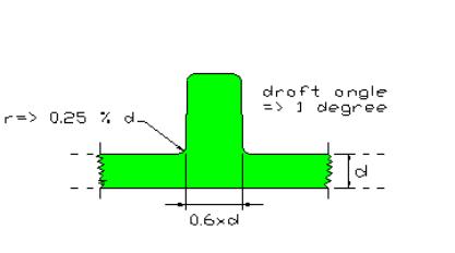
Figure 6-2 Typical Rib Design for LFT Compression
Molding
· Holes and open areas in a part can be accommodated with slides or cutouts. The use of slides will create flow-lines and potentially reduce the strength up to 50% in that area. Cutouts can avoid the compromise in mechanical properties with the resulting generation of scrap material. The cutout scrap can be reused in the same process since the materials are thermoplastic.
· Sharp edges and sharp radii should be avoided in part design. These can cause a high level of stress concentration, which in turn is often the reason for part failures. Sharp edges and transitions also increase fiber damage and create flow problems.
· Local shrinkage properties depend not only on the matrix shrinkage, but also on the local fiber orientation resulting from material flow in the tool. The shrinkage data in Table 6-1 can be used as a design guide for polypropylene (PP) and Nylon 6 (PA6). Material suppliers may be able to assist with specific shrinkage data in particular materials.
|
Resin |
Fiber |
Fiber Content in
wgt% |
Shrinkage in % |
|
|
In Flow Direction |
Against Flow Direction |
|||
|
|
|
|
|
|
|
PP |
Glass |
30 |
0.1 – 0.3 |
0.2 – 0.5 |
|
PP |
Glass |
40 |
0.1 – 0.2 |
0.1 – 0.3 |
|
PA 6 |
Glass |
30 |
0.1 – 0.2 |
0.3 – 0.5 |
|
PA 6 |
Glass |
40 |
0.1 – 0.2 |
0.2 – 0.4 |
Table 6-1 Shrinkage Data for some LFT Material
Requirements for LFT compression molding tools are similar to GMT compression molding requirements and to a certain extent to sheet molding compound and bulk molding compound (SMC/BMC) compression molding tools.
The most important guidelines are the following:
·
For production tools, tool steel is required. In some cases, aluminum can be used advantageously
depending on lifetime and cycle time constraints. For prototype tools Kirksite can be substituted for steel or
aluminum. Epoxy tooling can be used in
circumstances in which the parts require only vertical compression. If side
pressure is generated in a tool design, then an epoxy tool might break.
Therefore, epoxy tooling must be evaluated very carefully with respect to
anticipated loading, heat transfer properties, cost and durability.
· Shear edges specified on a compression molding tool should be
¨ Clearance: 0.02 mm
¨ Tolerance: + 0.02 mm
¨ Length of shear edge: 20 mm with 0 degree, then a 5 degree angle, and finally a radius at the end
· The mold cavity must be mechanically supported sufficiently to prevent deflection. If tool deflection under load is too great, then the volume of the cavity will increase and the part will not be filled with the right amount of material. When tool deflection is a problem, completely filled parts can only be achieved by increasing the material and also the thickness of the part. The resulting part will be either too heavy or poorly filled.
· Cooling channel zones should be designed to be as flexible as possible. The general rule is to avoid designing hot spots into the tool while maintaining symmetry. Asymmetric temperature profiles in a tool lead to warpage in the part. It is a practical advantage to have additional, separate cooling circuits for the vicinity of the shear edge as well as for the region where the charges will be placed. For larger tools, seven cooling circuits for each mold half are not unusual.
· Slides can be used as in injection molding tools.
· Ejector pins can assist to get trapped air out of the mold cavity during the filling process. Therefore, the choice of ejector pin locations and charge placement are critical in minimizing trapped air.
Glossary of Abbreviations and Acronyms
Cadpress Software for mold filling of long fiber thermoplastic composites, The Madision Group, Inc.
Copolymer Combination of two or more polymers into one molecular chain
Dynatup Trade name for an instrumented falling dart impact test
E glass Common grade of fiberglass used in commodity composites
Falling dart test Impact test defined in ASTM standard D-3029
GFXX Fiber glass, XX % by weight
GMT Glass mat thermoplastic composite
High melt flow Polymer with melt flow index greater than 50 g/10 minutes
Homopolymer Polymer consisting of similar subunits in the molecular structure
Izod test Impact test defined in ASTM standard D-256
Longitudinal Sample orientation in the direction of predominant fiber orientation
PA6 Nylon 6, polyamide
PE Polyethylene
PP Polypropylene
Random Material with fiber orientation equal in all directions
Size Coating applied to fiber bundles to assist with respect to handling and surface compatibility
Transverse Sample orientation orthogonal to predominant fiber orientation