
3.0 Identifcation of Weather Information Integration Strategies and Plan Preparation at TMCs
This section describes the support provided each of the five TMCs, identifies weather information integration strategies for each TMC, and summarizes the integration plans produced by the TMCs (complete plans are provided in the appendices).
3.1 TMC Self-Evaluation and Development of Weather Information Integration Plans
The consultant team provided varying levels of support for the five TMCs. With assistance provided through periodic conference calls and several site visits, the Tier 1 TMCs all completed the self-evaluation process and developed a weather integration plan. These plans are included in the appendices. The Tier 2 TMCs completed the self-evaluation process with significantly less support and identified weather integration strategies. One of the Tier 2 sites was able to develop an integration plan. The primary reason the other site did not develop a plan was the other demands placed on the TMC that were of higher priority.
Each TMC brought together a group of individuals representing specific functions within the TMC or an outside agency related to the process, to work through the self-evaluation process. These groups understood the range of TMC weather needs, the missions of the TMCs, and the value of establishing close working relationships with stakeholders outside the TMC. The varying perspectives from each member of these working groups were immensely valuable. New working relationships were established and weather information was shared.
The weather integration self-evaluation and planning process is illustrated in Figure 2. The process is divided into three major segments, each with a specific objective as shown in the figure. Segment 1, Self-Evaluation, concludes with a TMC identifying and prioritizing a set of weather related needs. Segment 2, Guidance for Weather Integration, maps the needs to a set of weather integration strategies and provides information about each strategy so that the TMC can select which ones best fit their most urgent needs and their operational constraints. Following selection of the strategies, the TMC is then encouraged to prepare an integration plan that describes in more detail what tasks they will perform to implement the selected strategies. All of the possible weather integration strategies by category and level are described in Table 8.
Twenty-three specific weather information/integration needs in five different categories are reviewed by the TMC as they progress through the self-evaluation process. Each TMC identifies the needs that are specific to its operation and approach to using weather information. Table 9 displays the list of needs including those each TMC in this study identified as its top priority. The table lists the Tier 1 TMCs’ needs that they selected to emphasize in the process of identifying their weather integration strategies; other secondary needs were also noted by these TMCs as they went through the self-evaluation process.
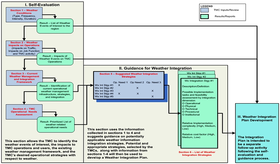
Figure 2. Weather Integration Self-Evaluation and Planning Process
Items of |
Strategies |
||||
|---|---|---|---|---|---|
Level 1 |
Level 2 |
Level 3 |
Level 4 |
Level 5 |
|
Use of Internal Weather Information Resources |
Camera imagery |
Radar, satellite, Automated Surface Observing System (ASOS) and Automated Weather Observing System (AWOS) data, and general zone-type forecast information |
Level 2 data plus data from Road Weather Information Systems (RWIS) and related networks |
Level 3 data plus data from Automatic Vehicle Locations/Mobile Data Computers (AVL/MDC) sources and internal radio communications |
Level 4 data with addition of analyzed fields and transformed data parameters (frost index, wind chill, est. snow, ice, water depth) |
Use of External Weather Information Sources |
General weather information, forecasts, and interpretation provided through media as irregular service (radio and TV weather) |
Internet provided, public access general forecasts, weather radar or satellite image or weather-specific broadcast channel |
Field observers or probes providing scheduled weather / driving condition information from entire route system |
Contractor provided surface transportation weather forecasts targeted at the operational needs of the TMC agencies |
Direct connection between private weather information service providers and traffic management software |
Availability of Weather Information |
Cable channel or subscription weather information vendor providing general weather information |
Internet provided weather radar or satellite image on video wall |
Field observers or Environmental Sensor Station (ESS) network providing scheduled road or driving condition reports |
Vendor provided daily surface transportation weather forecasts and observed weather conditions including Level 3 |
Meteorologist, located within TMC, forecasting and interpreting weather |
Frequency of Weather Forecasts |
Receive information of weather forecasts on a request basis |
Receive weather forecast once daily. |
Receive periodic forecasts several times a day |
Receive hourly updates of weather forecasts several times a day |
Receive continuous updates of weather forecasts in real-time |
Frequency of Weather/Road Weather Observations |
Receive information of weather conditions on a request basis |
Receive weather observations once hourly |
Level 2 plus receive weather/road weather observations when predefined thresholds have been exceeded |
Receive weather/road weather observations every ten minutes and when predefined thresholds have been exceeded |
Receive weather/road weather observations continuously with data above predefined thresholds highlighted |
Weather Information Coordination |
Intra-TMC committee tasked with weather information coordination |
Identified TMC or maintenance staff member tasked with coordinating weather information at TMC |
Dedicated weather operations supervisor |
Meteorology staff located within the TMC forecasting and interpreting weather information |
Co-location of the Emergency Operations Center/Office of Emergency Management (EOC/OEM) |
Extent of Coverage |
Sparse Set of Isolated Locations |
Network of Scattered Locations |
Corridor-level |
Multiple-corridor/sub-regional |
Regional/Statewide |
Interaction with Meteorologists and Climatologists |
Focus group or informal gatherings of local professionals from the transportation management and weather communities |
Develop check list of routine weather awareness activities |
Periodic staff meeting that includes a meteorologist to discuss weather information needs and responses |
With a meteorologist present conduct post-event debriefing / regular assessment to fine-tune responses |
Daily personal briefings and integrated interruptions by meteorology staff within the TMC |
Alert Notification |
Monitor media outlets, Internet page, or data stream for critical events |
Telephone call list |
Manual email/paging system |
Automated TMC road weather system-generated notifications (e.g., Email or page from Road Weather Information System or Flood Early Warning System) |
Automatic notification through Center-to-Center communications |
Decision Support |
Ad-hoc implementation of weather management strategies |
Use quick-reference flip cards on operator’s workstation to implement predefined response |
Response scenarios through software supply potential solutions with projected outcomes based on weather / traffic modeling |
Automated condition recognition and advisory or control strategy presented to operator for acceptance into ATMS |
Automated condition recognition and advisory or control strategy implemented without operator intervention |
Weather/Road Weather Data Acquisition |
Media Reports |
Internet and/or Satellite Data Sources |
Across agency intranet and dedicated phone acquisition |
Dedicated communications link to state, federal, private data sources |
Dedicated communications link to state, federal, private data sources including vehicle-derived weather data |
Weather Integration Needs |
Colorado Springs TMC |
Louisiana TMCs |
Kansas City Scout TMC |
|---|---|---|---|
Weather Integration Gathering and Processing |
|||
Better short-term forecasts of arrival time, duration, and intensity of specific weather cells (events) at specific locations |
|
|
|
Better prediction of impact of weather events including assessment of reductions in capacity |
|
|
|
Better real-time information on road conditions during weather events |
|
|
|
Improve the coverage and granularity of weather information in the region |
|
|
|
Assistance in interpreting weather information and how best to adjust operations in light of that information |
|
|
|
Institutional Coordination |
|||
Develop and implement clear, written policies and procedures for handling weather events |
|
|
|
Improve coordination within the TMC operations |
|
|
|
More coordinated responses and information sharing with adjacent jurisdictions/regions |
|
|
|
Improve coordination with local public safety and emergency agencies |
|
|
|
More opportunities and mechanisms for communications and exchange with others in the weather community and those with experience dealing with weather events |
|
|
|
Advisory Operations |
|||
Disseminate weather information to a larger set of stakeholders and users in the region (including transit and other modes) |
|
|
|
Improve message content (for DMS, 511, HAR, websites etc) |
|
|
|
Improve targeting of weather messages (site-specific, user group specific) to more effectively convey road weather information |
|
|
|
Provide better pre-trip weather information to aid travelers in their decision making |
|
|
|
Provide better en-route weather information to aid travelers in their decision making |
|
|
|
Control Operations |
|||
Improve management of emergency routing and evacuation for large-scale weather events |
|
|
|
Improve traffic diversion and alternate routing capabilities |
|
|
|
Improve safety at intersections during weather events |
|
|
|
Improve traffic signal timing during weather events to facilitate traffic movement |
|
|
|
Treatment Operations |
|||
Assist maintenance in better determining the optimal treatment materials, application rates, and timing of treatments. |
|
|
|
Improve the timeliness of weather management response including deployment of field personnel and equipment |
|
|
|
Reduce the time required to restore pre-event level of service operations after a weather event |
|
|
|
Reduce costs of roadway treatment options |
|
|
|
The subsections that follow summarize the efforts each TMC undertook to conduct a self-evaluation and develop an integration plan. The Tier 1 TMCs are described in terms of their operational characteristics, weather integration strategies (that correspond to their needs shown in Table 9), and the implementation plans that were created to guide their integration activities in the coming months and years. The Tier 2 TMCs are described by their efforts to conduct the self-evaluation and develop plans on their own.
3.2 Louisiana Statewide and Regional TMCs
3.2.1 Operational Characteristics
The regional and statewide Louisiana TMC operations staff work closely with one another to monitor and manage the operations of all interstate highways throughout the state. The TMCs operate Closed Circuit Television (CCTV) cameras, Dynamic Message Signs (DMS), Vehicle Detection (VD) devices, and the state’s 511/Condition Acquisition and Reporting System (CARS) traveler information system. The TMC Operations Staff also dispatch the Motor Assistance Patrol (MAP) vans, send notification emails to key personnel, and use Twitter to alert motorists of hazardous road conditions. TMC locations are shown in Figure 3.
Louisiana experiences a wide variety of weather patterns across the state that impact road safety and operations. Heavy rain events cause flooding of roadways, heavy fog impairs drivers’ visibility, tropical weather activity brings strong winds and heavy rains, and icy storms cause slippery roads. By integrating weather information into TMC operations, staff can inform drivers of hazardous weather conditions on the roads and aid in the reduction of weather-related vehicular accidents.
The Statewide TMC is located in Baton Rouge and oversees all field equipment and operations of the regional TMCs along with field equipment located in areas not covered by the regional TMCs. The Statewide TMC handles all regional based incidents and construction projects. It operates 24/7 and provides after-hour coverage for the regional TMCs.
The Shreveport TMC handles most of the northwest Louisiana area, including Shreveport and Bossier City and the surrounding areas. The interstates located within this area are I‑20, I-220, and I-49.
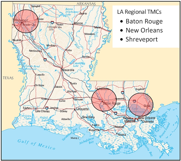
Source: Map provided by Louisiana TMC
Figure 3. Louisiana Regional TMCs
The Baton Rouge TMC covers East Baton Rouge Parish and surrounding areas including Denham Springs, Port Allen, and Prairieville. Several major interstates and junctions are located within the Baton Rouge area I‑10, I-12 and I-110.
The New Orleans TMC covers the greater New Orleans area, Kenner, Laplace, and the Northshore. I‑10 and I-610 are within the New Orleans area, and I-12 runs through Hammond and Covington on the Northshore.
All incidents or construction in these areas are handled by the regional TMC. Each TMC can assist in any incident by activating DMS, notifying key personnel, dispatching MAP and entering the incident into the 511/CARS system. The TMCs work cohesively to assure all incidents, construction and other projects are proficiently handled.
3.2.2 Weather Information Integration Strategies
The TMC operations staff was able to determine the levels of integration under which each TMC was operating and what intermediate levels needed to be achieved. Based on the needs selected, the target levels of integration were determined by the Guide. Intermediate levels were chosen to provide smaller steps to achieve the target level. Once the selected intermediate steps have been reached, the TMC operations staff will reassess how to approach the next level of integration. This process is repeated until the target level is achieved. Table 10 summarizes the current level of integration, selected intermediate level, and target level defined by the Guide.
Items of Integration |
Strategies |
||
|---|---|---|---|
Current Level |
Intermediate Level |
Target Level |
|
Use of Internal Weather Information Resources |
2 |
3 |
4 |
Use of External Weather Information System |
2 |
3 |
4 |
Availability of Weather Information |
2 |
3 |
4 |
Frequency of Weather Forecasts |
0 |
2 |
4 |
Frequency of Weather/Road Weather Observations |
0 |
2 |
4 |
Weather Information Coordination |
0 |
2 |
4 |
Extent of Coverage |
0 |
2 |
5 |
Interaction with Meteorologists and Climatologists |
0 |
2 |
3 |
Alert Notification |
1 |
1 |
4 |
Decision Support |
1 |
2 |
3 |
Weather/Road Weather Data Acquisition |
2 |
2 |
4 |
3.2.3 Implementation Plan
The self-evaluation and planning guide lists 11 separate integration strategies that pertain to different areas of weather integration in TMC operations. After reviewing all the strategies it was decided that many of these strategies could be implemented by utilizing the same resources; therefore, the TMC operations staff decided to combine these strategies and organize them in the order in which they were expected to occur. With the integration plan completed, weather integration would be implemented at each TMC during the next two years.
Several activities were planned to be initiated by the TMC operations staff during the implementation process. Most would begin with a written Memorandum of Understanding (MOU) and changes to policies and procedures. With these changes, the roles of the TMC Operations Staff when responding to weather-related events would change, becoming more proactive in response to road/weather information. Activities that were planned to be started at the TMCs during the initial integration of weather information included writing the policies and procedures to integrate weather and traffic information, coordinating with MAP operators and State Police on weather/road observations, and reporting.
Several projects were being implemented by the Department of Transportation and Development (DOTD) that included placing CCTV cameras and DMS in the New Orleans and Lafayette areas. With the installation of new equipment to inform travelers and to be able to monitor incidents and traffic, the TMC Operations Staff anticipated they would be better-equipped to handle weather-related events proactively. The first two years of the plan would be devoted to developing plans and policies and acquiring data in order to provide the necessary resources to manage weather events.
In the first 6 months the TMC Operations Staff planned to identify all weather information sources such as MAP, State Police, and Louisiana State University (LSU). These sources were discussed in the first through fifth and eighth integration strategies. The flow of information would be discussed, so the information could be received and properly used. The goals and plans of the TMCs would then be established, making all participating groups aware of them. Also within this timeframe a weather coordinator would be appointed to write, implement, and direct this plan.
Concurrent with the first set of goals, in the next 12 months, the TMC operations staff planned to develop policies and procedures. These policies and procedures would be developed in order for the flow of information to be utilized properly and efficiently. In these policies and procedures, definitions of advisory thresholds would be defined for statewide consistency. Although agencies and equipment would be different among the TMCs, the standard operating procedures would be the same for each TMC. Also during this time, the pilot sites would be established, and DOTD would develop detailed road device deployment plans for the sites which were discussed earlier, such as the Atchafalaya Bridge, Bonne Carre Bridge, and Red River Bridge.
Within the next 18 months, the pilot sites would be tested with RWIS equipment. During this time the weather coordinator would collect data, and the policies and procedures would be followed in order to ensure that the potential pilot sites were operating correctly. These pilot sites were intended to help determine the usefulness of the equipment and resources.
Within the next two years, the TMC Operations Staff would update the integration plan in order to identify the next steps in the weather integration process. Since the TMC operations staff chose an intermediate level, with the ultimate goal being the target level the Guide originally provided, the Guide would be revisited each year until the TMC operations staff and DOTD had made all the desired improvements for weather integration.
Table 11 lists the integration strategies previously discussed, implementation timeframe, and the sequence in which they should be reached.
Items of Integration |
Implementation |
Implementation |
|---|---|---|
Use of Internal Weather Information Resources |
1 year |
1 |
Use of External Weather Information System |
2 years |
2 |
Availability of Weather Information |
2 years |
2 |
Frequency of Weather Forecasts |
1 year |
1 |
Frequency of Weather/Road Weather Observations |
1 year |
1 |
Weather Information Coordination |
2 years |
3 |
Extent of Coverage |
5-10 years |
4 |
Interaction with Meteorologists and Climatologists |
2 years |
1 |
Alert Notification |
2 years |
3 |
Decision Support |
2-3 years |
3 |
3.3 Kansas City Scout TMC
3.3.1 Operational Characteristics
Kansas City Scout (KC Scout) is a comprehensive traffic congestion management and traveler information system conceived, designed, and operated jointly by two Departments of Transportation, a fact that is unique throughout the country. In September of 2001, the Missouri Department of Transportation (MoDOT) and the Kansas Department of Transportation (KDOT) jointly announced their bi-state initiative to address traffic impacts on over 100 miles of contiguous freeways intersecting both sides of the state line throughout the greater metropolitan Kansas City area.
KC Scout’s goal has been to offer area drivers the latest in technology and communications to help make their daily commute safer, faster and more manageable. Construction was already underway for MoDOT’s new District 4 Headquarters in Lee’s Summit, MO and it was decided that a state-of-the-art TMC could be housed within the new building. The Federal Highway Administration funded 90% of the initial $35.5 million start up costs, with the remaining funding for the project shared between both state DOTs.
The KC Scout TMC was completed and opened in late 2003 and has become recognized as an innovative leader in ITS deployment with an integrated system of 138 closed-circuit television cameras (CCTVs), 38 dynamic message signs (DMS), 277 vehicle detector stations (VDS), a highway advisory radio (HAR) system and a dynamic web site offering users the capability of designing their own customized alert messaging profiles.
The Kansas City Scout TMC began limited operations in January 2004 with 75 miles of coverage on portions of I‑70, I-435, I-35 and several state highways in both Missouri and Kansas. The official public launch was held during a ceremony on September 27, 2004 attended by city, state and federal officials along with media and emergency service providers.
Kansas City Scout encompasses the jurisdictional boundaries of Cass, Clay and Jackson counties in Missouri and Johnson and Wyandotte counties in Kansas. Population for those respective counties is as follows (Table 12):
County |
State |
Population |
|---|---|---|
Cass |
MO |
95,781 |
Clay |
MO |
206,957 |
Jackson |
MO |
664,078 |
Johnson |
KS |
516,731 |
Wyandotte |
KS |
155,509 |
KC Scout has maintained 24/7 operational hours since July 2005. Staffing levels vary between three shifts (6A-2P; 2P-10P and 10P-6A). Peak hours are staffed with a minimum of two operators and one floor supervisor. Due to the collocation of MoDOT’s customer service department within the TMC, information relayed to the public is also readily available to Scout operations.
Additionally, KC Scout is supported on both sides of the state line by motorist assist operations. They provide on-the-road assistance to motorists needing help with flat tires, low fuel, etc. and actively patrol the interstates looking for road hazards, tagging abandoned vehicles, and assisting with traffic control on incidents where lane restrictions have occurred due to stalls, accidents, traffic stops or weather impacts, such as flooding, ice covered bridges and overpasses, and debris from storm related events.
KC Scout’s coverage area is at the very crossroads of the nation’s network of interstate highways with 105 miles of monitored, contiguous roadways carrying high volumes of commercial, commuter and non-local motorists. Therefore, any weather conditions that affect the highways become of critical importance in terms of congestion, accident response, emissions, and driver impatience.
During winter storm events, MoDOT’s traffic department staffs a separate workstation within the TMC, solely for the purpose of monitoring road conditions and reporting on the snowplow activity within its local coverage area. This is of great assistance to KC Scout operations because the information can be used to post DMS messages in advance of the plows, helping to keep those lanes clear of through traffic that would otherwise impede plowing activity.
Figure 4 shows Average Annual Daily Traffic (AADT) for the freeway facilities on the Scout system.
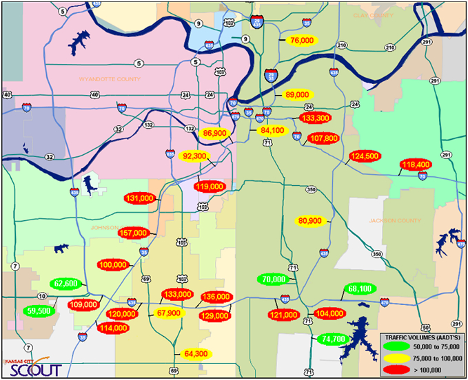
Source: Map provided by KC Scout
Figure 4. AADT Data as of September 2009
The I-70 interstate reaches across Missouri from the Illinois state line to the Kansas state line. It is the nation’s fifth largest east-west corridor, passing through 10 states from Maryland to Utah.
3.3.2 Weather Information Integration Strategies
KC Scout’s work with the Guide yielded a set of target strategies that identified the delta between where the TMC was and where they wanted to be in terms of weather information integration. Those results are shown in Table 13 below.
|
|
Guide Recommended Integration Level |
Chosen Weather Integration Level |
|
|---|---|---|---|---|
Use of Internal Weather Information Resources |
2 |
3 |
3 |
RWIS to be deployed in Missouri in 2010 |
Use of External Weather Information Resources |
2 |
4 |
3 & 4 |
Utilizing field and contractor provided data |
Availability of Weather Information |
2 |
4 |
3 & 4 |
Utilizing field and vendor provided daily surface info |
Frequency of Weather Forecasts |
4 |
4 |
4 |
Hourly updates several times a day is reasonable |
Frequency of Weather/Road Weather Observations |
3 |
3 |
3 |
Observations hourly or whenever pre-determined thresholds are exceeded |
Weather Information Coordination |
0 |
3 |
1 & 2 |
Project team will remain active with project coordinator from TMC |
Extent of Coverage |
0 |
5 |
1 & 2 & 3 |
Coverage up to corridor level |
Interaction with Meteorologists |
0 |
3 |
1 & 2 & 3 |
Informal meetings, informational checklists and scheduled sessions with Meteorologist from NWS |
Alert Notification |
1 |
4 |
4 |
RWIS generated data received electronically |
Decision Support |
1 |
3 |
3 |
Utilization of ‘what if’ scenarios for training and projected outcomes |
Weather/Road Weather Data Acquisition |
2 |
3 |
3 |
Intra-agency and dedicated hotline for notification and advisories |
3.3.3. Implementation Plan
Implementation planning is intended to address the steps necessary to achieve their high need objectives. The six target strategies included:
- Disseminate weather information to a larger set of stakeholders and users in the region (including transit and other modes)
- Provide better en-route information on weather conditions to aid travelers in their decision-making
- Develop and implement clear, written policies and procedures for handling weather events
- Improve the timeliness of weather management response including deployment of field personnel and equipment
- Provide assistance in interpreting weather information and how best to adjust operations in light of that information
- Create better real-time information on road conditions during weather events.
Many of the selected strategies involved tasks that were moderate in terms of their complexity and cost to implement. These involved readily available data link connections from external sources and internally developed policies and procedures. In cases where equipment had to be purchased, installed and maintained (i.e., RWIS or Automated Vehicle Location (AVL)/Mobile Data Computer (MDC)) the costs were justified in terms of the added level of service Scout would be enabled to provide.
Scout’s TransSuite™ ATMS Software. Providing the core platform for Scout’s TMC operation is its state-of-the-art ATMS. Within this framework, CCTVs, DMS and VDS are controlled and monitored.
Prior to September 2009, Scout used a UNIX-based system that furnished little support for enhancement development, report generation or operator efficiency. Many manual workarounds were developed by Scout staff that were time consuming to create and maintain but provided the level of utility desired to create and monitor incidents, track and trend activity, and provide management reporting capabilities. Inbound weather information consisted of daily MoDOT radio broadcasts of WeatherOrNot™ furnished forecasts or Internet-based weather media channels monitored on individual desktops. Scout operators became adept at identifying changing weather conditions while constantly monitoring CCTV cameras spanning 100-plus miles of interstate in the metro KC area. Weather information was more than just a component of the ATMS architecture platform.
On September 1, 2009, Scout successfully deployed TransSuite™ ATMS software. This represented the first major update to Scout’s core ATMS platform since the TMC began formal operation in January of 2004. The effort resulted from two years of detailed planning, needs assessment and testing, largely driven by what had been lacking in the legacy system, i.e., scalability, adaptability and ease-of-use. The Windows/SQL-based TransCore™ product deployment was nearly seamless and has streamlined all the processes associated with creating and monitoring traffic incidents, activating and updating DMS message boards and linking all pertinent incident information into easily accessible databases and reporting tools. The user-interface utilizes a series of “layers” that visually represent infrastructure (CCTVs, DMS, VDS), traffic incidents, scheduled events (roadwork) and special events (heavy traffic stadium/concert events).
With this added flexibility, Scout will soon be able to integrate weather information into the user-interface as another “layer” utilizing the lat/long data link connectivity available from external weather information sources, e.g. NOAA, National Weather Service’s (NWS) National Digital Forecast Database (NDFD), and Meridian-511 providers. As an example, when a weather condition exists that meets pre-selected alert threshold criteria, a “layer” will “activate” on the operator’s ATMS desktop map application, signaling creation of a weather event type “incident” with applicable DMS messaging and outputs to Scout’s website and subscriber-configured WebAlert applications. The quickness of being able to notify motorists of a rapidly developing severe weather condition will aid in their decision-making and hopefully reduce severe weather related crashes on the interstate. The next upgrade will accommodate this added weather data functionality. Training on the use of these new elements will require TMC staff development along with support system documentation, but the resources currently exist to complete these efforts.
Partnerships between Stakeholders. Partnerships between stakeholders are well established. Scout’s Board of Directors has endorsed this project as a planning mechanism, but all proposed changes would first need to be reviewed and approved before any formal implementation can begin. This board meets every three months but opportunities exist to communicate with them as needed. The board reviewed the Implementation Plan at its meeting on March 25, 2010.
Summary of the Implementation Plan. Figure 5 identifies the specific tasks to be accomplished to achieve the Implementation Plan objectives identified at the beginning of this section. Also the figure illustrates the timeline of activities for each task. Table 14 identifies each task with key inputs and outputs, along with the key responsible KC Scout staff assigned. The information contained in Figure 5 and Table 14 will be used to guide the activities to successfully implement the weather integration tasks.
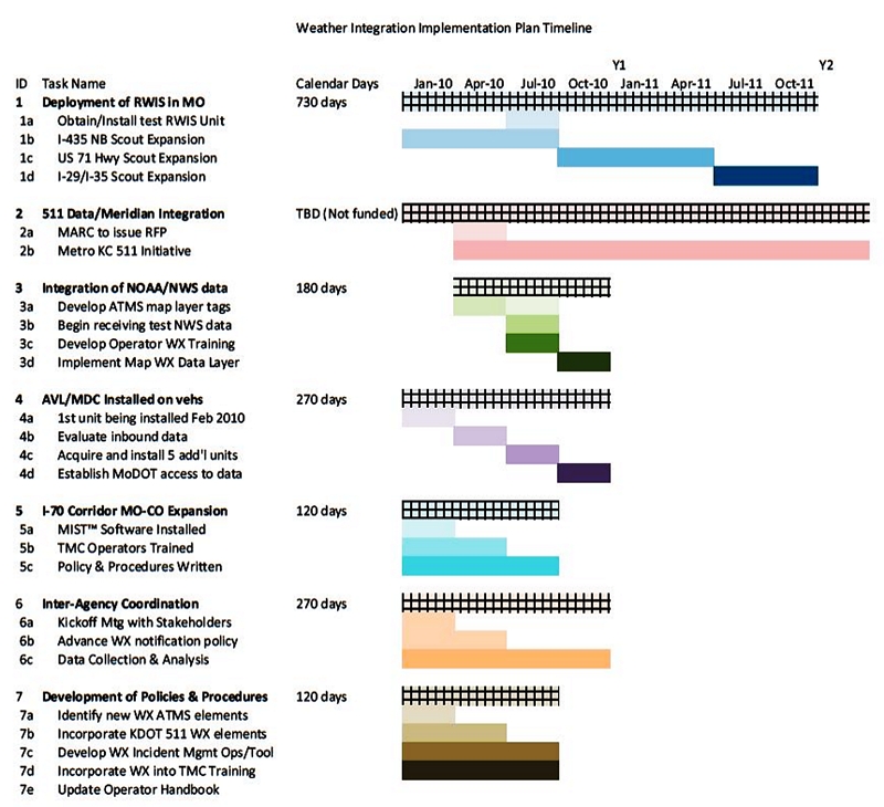
Figure 5. Implementation Timeline
ID |
Task Name |
Owner |
Inputs |
Outputs |
Proposed |
Current Status |
|---|---|---|---|---|---|---|
1 |
RWIS Deployment (MO) |
Jason Sims |
Contracts awarded |
-Realtime Wx data |
January 2010 Start (as part of current construction activity on three (3) Scout expansion projects |
Delayed to spring 2011, due to need to get power to selected locations |
2 |
Meridian Data Integration from 511 (KS/MO) |
Barb Blue |
Existing KDOT 511 data |
-Link to Scout website/ATMS |
KDOT 511 data available now |
KDOT 511 in use and mobile app now offered/ |
3 |
Integration of NOAA datasets enabling alert notification of impending adverse weather conditions |
Don Spencer |
-GIS shape files |
-ATMS Map Layer |
Spring 2010 |
Expect to implement summer 2011 and available by fall 2011 |
4 |
AVL/MDC installed on MA/ER vehicles |
Jason Sims |
-Road condition data elements |
-Real-time Wx information |
Single evaluation unit to be installed March of 2010 |
Deployed in 1/3rd of fleet, with balance pending funding |
5 |
I-70 Corridor Mgmt (from MO to CO) |
Jason Sims |
-KDOT Maint & Ops notification of Wx events |
-Activation of KDOT Wx messaging and CCTV monitoring |
Spring 2010 |
MO cameras and DMS fully integrated into ATMS by summer 2011 |
6 |
Inter-Agency Coordination |
Jason Sims |
KDOT, MoDOT, NDOR |
-Proactive Wx messaging |
Summer 2010 |
On-going integration through ATMS |
7 |
Development of Policies and Procedures Relative to Weather Integration |
Nancy Powell |
-Integrated weather layer within ATMS software |
-Incorporate weather incident mgmt into standard operating procedures and training manuals |
Summer 2010 |
On-going, Prelim report expected summer 2011 |
3.3.4 Post-Implementation Evaluation Planning
As KC Scout continues to deploy their weather integration strategies, they are developing a Post-Implementation Evaluation Plan. Their intent is to assess the ability of their ATMS with integrated weather information to help their operators initiate the actions necessary to proactively respond to forecast weather events through their ATMS, activate the appropriate DMS signage from a predetermined library of approved messages, and manage the event effectively. The expectation is that this system with its enhanced and integrated weather information will result in timelier messaging for the traveling public, along with more proactive internal sharing of weather information between operations and maintenance, and will result in improved highway performance and traveler safety. Figure 6 was used in a meeting with KC Scout to help guide the early planning to evaluate the performance of their ATMS with fully integrated weather information.
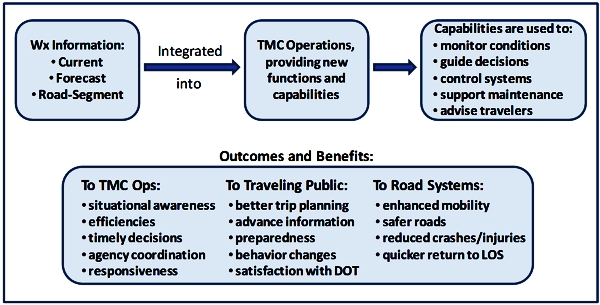
Figure 6. Pathway to Benefits from KC Scout’s ATMS Integrated with Weather Information
Although the evaluation plan is not yet prepared, KC Scout is working on how to structure the evaluation. Elements that are under discussion and development at KC Scout include:
- The importance of assuring that the integrated ATMS system is fully functional, that operators have been trained in the use of any new components associated with the acquisition, integration, processing and dissemination of weather information, and enough time has elapsed that the use of the new system has become relatively routine for the operators; that is, with assurance that all or most of the “bugs” have been eliminated.
- The establishment of a fully-functional weather alert notification capability, with alert trigger thresholds that have been defined, implemented, and tested under real world conditions. Ideally, KC Scout will also have new procedures in place that guide the operators in the use of the system and their responses to weather alerts under varying conditions.
- Selection of the evaluation design that will be most appropriate to assessing the achievement of the desired outcomes, allowing KC Scout to attribute the measured outcomes to the effects of their weather integration program, and controlling for the effects of outside factors unrelated to weather integration (for example, other programs that have been developed that might also impact those outcomes, or variability in weather conditions that impact response times and other measured indicators).
- Identification of data requirements to support the evaluation, including sources of data, and specification of the time periods over which data will be needed, both for baseline conditions and post-deployment (if using a “before-after” evaluation design).
- Agreement on the measures of performance effectiveness that will be used in the evaluation to assess the benefits of weather information integration in their operations. Measures of effectiveness are being framed based on the following desired outcomes:
- Timely posting and removal of weather event messaging to affect motorist behavior
- Timely communication of weather information to internal and external parties
- Improvements in maintenance performance due to more proactive weather alerting
- Savings in areas of maintenance labor and costs associated with shortened time to achieve Level of Service (LOS) linked to the benefits of weather information received from the TMC
- Reduction in the number of weather-related incidents at high accident locations
- Improvement in response times to weather related incidents by DOT responders
- Improvements in the level of customer satisfaction
KC Scout expects their new weather integration system to be operational in summer 2011. The evaluation plan should be complete at this time as well. The system will be tested through the remainder of this winter and through the summer months (strong thunder storms, etc.). The evaluation of the system will continue through April 2013 in order to capture data for two complete seasons.
3.4 Colorado Springs TMC
3.4.1 Operational Characteristics
The Colorado Springs Traffic Management Center (CSTMC) is very unique compared to the other centers in Colorado. It is a regional facility that covers the Pikes Peak region in El Paso County, CO. The center is run and operated by the City of Colorado Springs Traffic Engineering Division instead of by the Colorado Department of Transportation (CDOT). The CSTMC facility houses the Intelligent Transportation System (ITS) equipment and personnel. The ITS equipment includes the signal timing equipment and the computer systems to operate the traffic cameras and Variable Message Signs (VMS). Figure 7 shows a map of Colorado Springs.
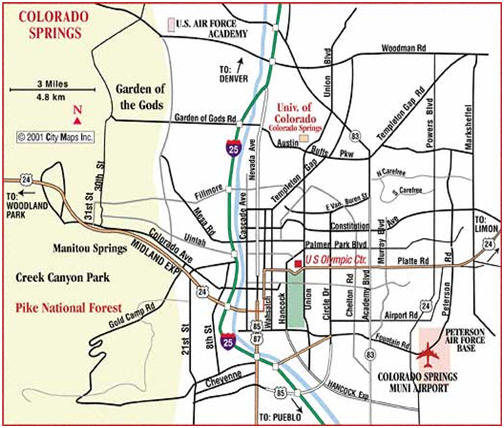
Source: Map provided by Colorado Springs, Colorado TMC
Figure 7. Regional Map of Colorado Springs
All fiber communications are managed in the CSTMC. Some of the factual data for the center and the Pikes Peak region include:
- CSTMC incorporates the management and oversight of nearly 564 traffic signals in Colorado Springs.
- The center is open Monday through Friday from 6:30 am until 6 pm. During those hours the City of Colorado Springs is responsible for managing and controlling all the transportation management devices in the region, including the cameras and variables message signs on the I‑25 Corridor. The after-hours control of the VMS reverts to the Colorado Statewide Transportation Management Center (CTMC). The after-hours traffic signal control is managed by the City of Colorado Springs through an emergency callout procedure. While the CSTMC is open from 6:30 am until 6 pm, the traffic signal technicians work between 7:30 am – 5:30 pm.
- The CSTMC has a total of 63 cameras and 47 VMS. There are 29 cameras and 31 VMS on I-25. The other cameras and VMS are on arterial roadways.
- There are 28 miles of coverage on I-25 in the Pikes Peak region with approximately 100,000 annual average daily traffic including 8% truck traffic.
- The population in the region is approximately 400,000.
- There are 1,300 roadway miles in Colorado Springs.
- The elevation in Colorado Springs ranges from 6,000 to around 7,000 feet. The highest elevation location on I-25 is on Monument Hill at approximately 7,300 feet.
- The City’s Street Division is responsible for servicing over 7,423 lane miles of roadway, extending over a 196 square mile area. The services performed by the Street Division include pavement repairs and maintenance as well as snowfall removal.
- The average annual snowfall is 42 inches.
The CSTMC collects and distributes traffic information. The most common dissemination methods include VMS, Twitter and media releases. The types of traffic information include:
- Traffic Incidents (crashes, stalls, debris, etc.)
- Road work
- Major congestion
- Road weather conditions impacting driving
- Highway/street closures for emergency calls (fire, police, utilities)
- Power/traffic signal outages
- Fires (controlled burns, structure fires, vehicle fires and wildfires)
- Special events (parades, graduations, races, USAFA events, World Arena Events, etc.)
- Traffic campaigns in the State (DUI/seatbelt)
- Accident Alert Status (Cold reporting) for the Colorado Springs Police Department (CSPD) and Colorado State Patrol (CSP)
- Chain law restrictions for commercial vehicles for Monument Hill
- AMBER Alerts
The CSTMC is responsible for traffic signal timing and traffic signal coordination. The computerized Traffic Control System (TCS) allows city staff to continually evaluate and coordinate the City's traffic signals. The City Traffic Engineering staff studies and re-evaluates approximately 30 to 40 arterial streets each year for optimal coordination. The goal of traffic signal coordination is to progress the greatest number of vehicles through the system with the fewest stops and shortest amount of delay.
The traffic signal timing team is comprised of the City's Traffic Engineer and traffic signal technicians who specialize in the timing and coordination of the traffic signals. They gather data, evaluate, and study the major and minor arterial streets. They drive the arterial before and after the new coordination timing is applied to determine the effectiveness and efficiency of the new coordination.
Coordinated signals attempt to provide green lights for the major vehicle flow on a street. This requires that city staff gather data on the volume, speed, distance between signals, and the timing of individual intersections. When the data have been collected a study is done to determine the best timing and coordination of all intersections involved. This may require the timing of the intersections to be adjusted to facilitate the best flow of vehicles.
When the best coordination has been determined the team will implement the new timing plan. Studies are conducted to evaluate the efficiency and to make necessary adjustments. Coordination throughout the city is continually monitored and is reevaluated as needed.
Each arterial has special coordination needs and may require that various types of special timing plans be implemented to help the flow of traffic. To accommodate heavy travel demand periods, it may be necessary to have a long cycle length, and this may cause delays on the side streets. Some arterials may have a heavier flow in one direction. This movement may be favored, causing more stops in the less traveled direction. Some intersections may have lagging left turn movements. This means the left turn arrow comes on at the end of the green through light. There may also be planned stops on long arterials to help maintain the flow of vehicles.
Effective coordination greatly improves the flow of vehicles on the arterial by minimizing the interruption of traffic flow and reducing air pollutants. Other than placing a traffic signal in recall when video camera detection is iced over, the effects of weather on traffic flow have not been considered when establishing signal timing plans in the past. The weather integration plan will allow the staff to develop strategies for modifying signal timing plans in response to specific weather events.
A variety of weather in the region provides a significant challenge to motorists, highway maintenance and traffic signal crews. It also creates havoc with TMC equipment including the traffic signals detection cameras and the highway cameras. The weather systems effecting travel include winter snow storms, high winds, thunderstorms, street flooding and fog conditions.
The climate is very unique within the 194 square miles of the Colorado Springs city limits. While there is only a slight change in elevation in various parts of the city, the actual weather and road conditions can be drastically different at the same time in various locations in the city limits. The weather conditions in the spring and summer produce high winds, thunderstorms with flooding and lightning strikes and foggy conditions. The fall and winter produce high winds, snow storms with blowing snow, heavy snow and occasional extreme low temperatures and occasional foggy conditions.
Weather forecasting information is available from a variety of sources. The CSTMC operators have no set schedule to check the various sources of information.
3.4.2 Weather Information Integration Strategies
The CSTMC analyzed each integration strategy based on the current integration level and the Guide-recommended integration level based on the high priority needs identified in Table 9 above. The CSTMC personnel then determined a chosen weather integration level based on what was thought to be most feasible for the CSTMC. The integration strategies are listed in Table 15 below.
Integration Item |
Current |
Guide |
Chosen |
|---|---|---|---|
Use of Internal Weather Information Resources |
1 |
4 |
3 |
Use of External Weather Information Resources |
2 |
4 |
3 |
Availability of Weather Information |
2 |
4 |
4 |
Frequency of Weather Forecasts |
1 |
4 |
3 |
Frequency of Weather/Road Weather Observation |
1 |
4 |
3 |
Weather Information Coordination |
None |
4 |
2 |
Extent of Coverage |
4 |
5 |
4 |
Interaction with Meteorologists |
None |
3 |
2 |
Alert Notification |
1 |
4 |
3 |
Decision Support |
1 |
3 |
2 & 3 |
Weather/Road Weather Data Acquisition |
2 |
4 |
3 |
3.4.3 Implementation Plan
The plan for the CSTMC is to create operator-initiated signal timing plans based on weather observations and predictions. The process involves utilizing the City of Colorado Springs Street Department grid map and performing signal timing modification in each of the 16 grids. It is also a future goal to develop an automated modified signal timing plan in any or all of the 16 grids for weather related incidents. The automation can help reduce the need for after- hour staffing to manage the system.
The CSTMC has elected to conduct a pilot program and the timeline is outlined below. The plan is to utilize just a single grid from the 16 grids available. The project will include fine tuning and evaluating the signal timing plan in the grid selected. At the completion of the pilot project the signal timing plans can be implemented in all 16 grids.
The tasks are split into two categories. One is the weather integration related tasks and the other is traffic signal timing pilot project tasks. Each task and the proposed time frame for both start and completion are listed below in Table 16. Since this timeline was prepared, the demands on limited staff have caused the dates to be pushed out about a year to mid-2011. The pilot test is now expected to be initiated in the spring of 2011, and in anticipation of that, the TMC has begun training technical personnel, and they have installed and are testing several new cameras at selected intersections.
ID |
Weather Integration Related Tasks |
Start |
Finish |
|---|---|---|---|
A1 |
Collect baseline data in specified locations/grids |
12/09 |
03/10 |
A2 |
Refine concept of operations and identify what weather information is needed |
01/10 |
02/10 |
A3 |
Obtain training for weather coordinator |
01/10 |
02/10 |
A4 |
Establish data triggers, notifications and actions |
02/10 |
05/10 |
A5 |
Make adjustments to TMC displays to include cameras, radar and satellite |
05/10 |
07/10 |
A6 |
Prepare standard operating procedures |
08/10 |
09/10 |
A7 |
Alert notification to the motorist on weather conditions |
On-going |
|
ID |
Traffic Signal Timing Pilot Project Related Tasks |
Start |
Finish |
B1 |
Identify performance measures and prepare plan |
04/10 |
05/10 |
B2 |
Develop signal timing plans based on new weather information |
05/10 |
08/10 |
B3 |
Provide training for signal technicians on new procedures |
09/10 |
10/10 |
B4 |
Implement signal timing pilot project with automation |
11/10 |
03/11 |
B5 |
Evaluate effectiveness |
11/10 |
05/11 |
NOTE: The indicated start and finish dates have slipped approximately one year since this schedule was prepared.
3.5 Wyoming Statewide TMC in Cheyenne
The statewide TMC in Wyoming is one of the Tier 2 sites that received limited support for their weather information integration self-evaluation and planning process. They undertook the process on their own and prepared a weather integration plan that they are currently beginning to implement. Their operational characteristics, integration strategies, and implementation plan are discussed below.
3.5.1 Operational Characteristics
Wyoming DOT’s (WYDOT) statewide TMC became operational in the fall of 2008. The TMC is housed in the basement of the Qwest building at 6101 Yellowstone Road in Cheyenne, Wyoming, approximately a mile north of the WYDOT headquarters complex. The TMC houses both the emerging ITS operations function and a new dispatch center for the Wyoming Highway Patrol.
While numerous states already have similar TMCs in operation to deal with urban traffic congestion, Wyoming’s center is geared almost exclusively toward rural travel management and information needs that result from extreme weather conditions. Additionally, it is one of the few TMCs where communication services for DOT construction, traffic, and maintenance functions are co-located with law enforcement. The functions of the TMC have expanded over time, but the core functions can be grouped into the following four main areas:
- Monitoring and control of roadside ITS devices such as web cameras, RWIS, Variable Speed Limit (VSL) signs, DMS, HAR, flashing beacons, and road closure gates;
- Serving as a law enforcement communications hub for state and federal agencies by maintaining frequent contact with Highway Patrol troopers and other personnel via the State Law Enforcement Communications Systems (SALECS);
- Managing communication with the traveling public via the 511 Travel Information Service (telephone and internet components) and direct contact with media outlets, visitor centers, and truck stops;
- Receiving and relaying road and weather reports from volunteers participating in the Enhanced Citizen-Assisted Reporting (ECAR) program, as well as, dispatching WYDOT construction and maintenance crews throughout the state.
Currently, WYDOT has a network of 62 RWIS stations located throughout the state. They are managed by a central software system known as SCAN Web. Figure 8 and Figure 9 that follow are screen shots from that software, showing the statewide network, followed by a more detailed map of southeast Wyoming where WYDOT has deployed a greater density of RWIS for a 52-mile VSL corridor between Laramie and Rawlins.
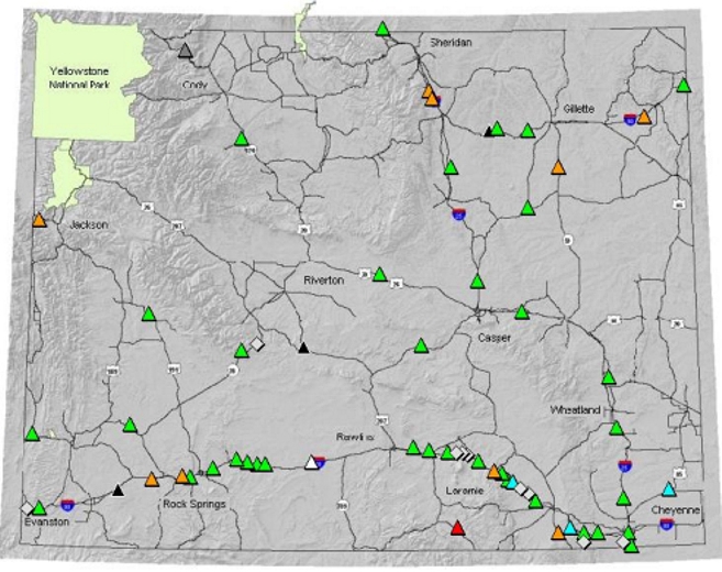
Source: Screen shot from WYDOT’s SCANweb system.
Figure 8. RWIS Locations Statewide
The VSL corridor is the first of its kind in Wyoming. It consists of a 52-mile stretch of Interstate 80 from Walcott Junction (20 miles east of Rawlins) to Quealy Dome Interchange (17 miles west of Laramie). In that 52-mile corridor, WYDOT now has 13 RWIS stations. This project represents the first corridor-level RWIS deployment in WYDOT’s history.
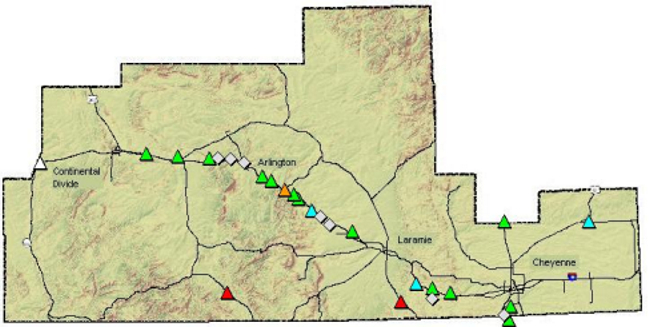
Source: Screen shot from WYDOT’s SCANweb system.
Figure 9. RWIS in Southeast Wyoming
3.5.2 Weather Information Integration Strategies
Table 17 provides a summary of WYDOT’s integration strategies. The table shows WYDOT’s current level for each integration item, the recommendation from the self-evaluation guide, the integration level selected by WYDOT for both the current (C) timeframe, and future (F) timeframe, and comments for each integration item.
Integration Item |
Current Integration Level |
Guide Recommended Integration Level |
Chosen Weather Integration Level |
Rationale/Comments |
|---|---|---|---|---|
1: Use of Internal Weather Information Resources |
3 |
3 |
3/4 |
C=expand RWIS locations; F=outfit & receive data from plows & other vehicles |
2: Use of External Weather Information Resources |
4 |
4 |
4/4 |
Build integrated weather information tool to assist TMC operators |
3: Availability of Weather Information |
4 |
4 |
4/4 |
Availability meets current needs |
4: Frequency of Weather Forecasts |
4 |
4 |
4/4 |
Frequency meets current needs |
5: Frequency of Weather/Road Weather Observations |
2 |
3 |
3/3 |
Expand coverage and frequency of plow driver reports |
6: Weather Information Coordination |
None |
3 |
3/3 |
Contracting with a part-time local meteorologist to perform weather information management tasks in TMC. |
7: Extent of Coverage |
2 |
4 |
4/5 |
C=Adding four more VSL corridors throughout the state; F=continued expansion of RWIS sites. |
8: Interaction with Meteorologists |
1 |
3 |
4/5 |
See item 6 above. |
9: Alert Notification |
4 |
4 |
4/4 |
Enhance alert notification in phases (use |
10: Decision Support |
1 |
3 |
3/4 |
C=automated recommendations for VSL system; F=expand to DMS recommendations. |
11: Weather and Road Weather Data Acquisition |
4 |
4 |
4/5 |
C=continue current acquisition; F=automated data collection from DOT vehicles. |
*C/F=Current plans (within next 1-2 years)/Future plans (beyond 2 years)
3.5.3 Implementation Plan
The integration strategies can be grouped into the following seven implementation tasks or projects:
- RWIS Expansion - Expand RWIS coverage throughout state, and multiple corridor RWIS projects. Start by doing a gap analysis, and seek input from District Maintenance offices to determine desired locations. With that, WYDOT can develop an RWIS expansion plan, and budget for new RWIS on an annual basis to complete the desired expansion in approximately the next five years.
- AVL/MDC - Expand vehicle weather data transmission to TMC from plows with AVL/MDC. This will include continued deployment of their current AVL system statewide. For the MDC component, WYDOT will use its systems engineering process to ensure all requirements are met, including integration with the current AVL system.
- Weather Information Manager (WIM) - Employ part time, contracted meteorologist as weather information manager. This individual will help implement much of this plan, assist the TMC operators in managing and utilizing current and future weather information, and provide a primary point of contact for all weather information resources within WYDOT.
- VSL Expansion - Add Variable Speed Limit (VSL) in four locations and continue to expand in statewide corridors. One of these four new corridors, a VSL project in the Rock Springs - Green River corridor on Interstate 80, was completed and became operational on January 31st, 2011. Two more of these four will be operational by October 2011, and the fourth corridor is currently schedule to be constructed in 2012.
- Weather Information Tool - Build integrated weather information tool to assist operators. Deploy portions of this for commercial vehicle and general public use. The weather information manager will be instrumental in developing this system. That person will also be responsible for keeping the information in this tool timely and accurate.
- Weather Alert Notification - Expand/enhance alert notification system in phases: 1) using SCAN Sentry 2) expanding METalert system 3) using the new integrated weather integration tool/database. SCAN Sentry is presently available to the TMC; it just needs some fine tuning on the configuration and some additional training for the operators. METalert is also available, but additional features (e.g. visibility alerts) could be very useful for the TMC operators.
- ATMS Decision Support - Expand decision support tools, starting with VSL and moving to DMS recommendations. This will include some software development work for our existing ATMS to provide such recommendations based on weather and traffic information.
Table 18 shows the schedule and estimated cost (initial and O&M) for each of the seven projects identified above.
Project |
Start |
Completion |
Initial Cost |
O&M Cost |
|---|---|---|---|---|
RWIS Expansion |
Ongoing |
2015 |
$ 2,000,000 |
$ 400,000/year |
AVL/MDC |
2011 |
2017 |
$ 800,000 |
$ 100,000/year |
WIM |
Ongoing |
N/A |
N/A |
$ 100,000/year |
VSL Expansion |
Ongoing |
2014 |
$ 3,000,000 |
$ 200,000/year |
Wx Info Tool |
2011 |
2013 |
$300,000 |
$15,000/year |
Wx Alert Notification |
Ongoing |
2013 |
$20,000 |
$3,000/year |
ATMS Decision Support |
2011 |
2013 |
$150,000 |
$15,000/year |
Many of these projects are underway and at least partially funded. The scopes of these projects may need to be slightly re-defined to meet the needs identified in WYDOT’s plan.
3.6 Redding, California TMC
The Caltrans District 2 TMC located in Redding, California is the second Tier 2 TMC that received limited support for their integration planning. They conducted their self-evaluation using the Guide, and identified a set of weather information integration strategies consistent with their indicated priority needs. However, the pressing immediate demands on their time and resources to operate the TMC did not allow them to prepare an integration plan.
The Redding TMC identified a list of weather information integration strategies that are presented below. It is uncertain whether these strategies will be implemented at the TMC.
3.6.1 Weather Information Integration Strategies
Table 19 provides a summary of Caltrans District 2 TMC integration strategies. The table shows their current level for each integration item, the recommendation from the self-evaluation guide, the integration level selected by Caltrans, and comments for each integration item. Their chosen weather integration level by integration item was fairly conservatively identified due mainly to extremely constrained resources to support implementation. As shown in the table, many of the integration items were not addressed and would need to be considered as possible future items.
Integration Item |
Current Integration Level |
Guide Recommended Integration Level |
Chosen Weather Integration Level |
Rationale/Comments |
|---|---|---|---|---|
1: Use of Internal Weather Information Resources |
3 |
4 |
|
Possible future consideration |
2: Use of External Weather Information Resources |
3 |
4 |
|
Possible future consideration |
3: Availability of Weather Information |
3 |
4 |
|
Possible future consideration |
4: Frequency of Weather Forecasts |
3 |
4 |
|
Possible future consideration |
5: Frequency of Weather/Road Weather Observations |
2 |
4 |
3 |
Bring more Wx info, more often, into the TMC. |
6: Weather Information Coordination |
none |
4 |
1 |
Combine with Item 8. Establish coordination committee within the TMC. |
7: Extent of Coverage |
4 |
4 |
|
Possible future consideration |
8: Interaction with Meteorologists |
1 |
3 |
2 |
Combine with Item 6. Establish relationships with NWS and obtain assistance. |
9: Alert Notification |
2 |
4 |
|
Possible future consideration |
10: Decision Support |
1 |
3 |
2 |
Prepare quick reference flip cards |
11: Weather and Road Weather Data Acquisition |
3 |
4 |
|
Possible future consideration |