CONDUCTED BY:
THE PENNSYLVANIA DEPARTMENT OF TRANSPORTATION
BUREAU OF CONSTRUCTION AND MATERIALS
ENGINEERING TECHNOLOGY AND INFORMATION DIVISION
NEW PRODUCT EVALUATIONS AND RESEARCH SECTION
The Pennsylvania Department of Transportation and the U.S. Department of Transportation, Federal Highway Administration, sponsored this work. The contents reflect the views of the author who is solely responsible for the facts and the accuracy of the data presented herein. This report does not necessarily reflect the official views or policies of the Pennsylvania Department of Transportation or the Federal Highway Administration and does not constitute a standard, specification, or regulation. The Pennsylvania Department of Transportation and the Federal Highway Administration do not endorse products, processes, or manufacturers; trademarks or manufacturer's names appear herein only because they are considered essential to the object of this report.
NSN 7540-01-280-5500
This final report completes the evaluation of the Evergreen Wall System in Engineering District 6-0 on the "Blue Route", SR 0476, Delaware County. The I-476 interstate project was constructed in five sections. May 3, 1991. The prime contractor on this section was G.A. & F.C. Wagman Inc.
REPORT DOCUMENTATION PAGE
Form Approved
OMB No. 0704-0188
Public reporting burden for this collection of information is estimated to average 1 hour per response, including the time for reviewing instructions, searching existing data sources, gathering and maintaining the date needed, and completing and reviewing the collection of information. Send comments regarding this burden estimate or any other aspect of this collection of information, including suggestions for reducing this burden, to Washington Headquarters Services, Directorate for Information Operations and Reports, 1215 Jefferson Davis Highway, Suite 1204, Arlington, VA. 22202-4302, and to the Office of Management and Budget, Paperwork Reduction Project (0704-0188) Washington, DC 20503.
1. Agency Use Only (Leave Blank)
2. Report Date
August 1998
3. Report Type and Dates Covered
FINAL REPORT May 1986 - August 1998
4. Title and Subtitle
EVERGREEN RETAINING WALL SYSTEM
5. Funding Numbers
6. Author(s)
John Hughes
7. Performing Organization Name(s) and Address(es)
Pennsylvania Department of Transportation
Bureau of Construction and Materials
Engineering and Information Technology Division
1118 State Street
Harrisburg, PA 17120
8. Performing Organization Report No.
84-104A-B
9. Sponsoring/Monitoring Agency Name(s) and Address(es)
10. Sponsoring/Monitoring Agency Report Number
U.S. Dept of Transportation
FHWA
Division of Research
400 - 7th Street, SW
Washington DC 20590
Pennsylvania Department of Transportation
Bureau of Planning and Research
555 Walnut Street
6th Floor Forum Place
Harrisburg PA 17101-1900
FHWA-PA-97-011+84-104
11. Supplementary Notes
Program Manager:
Organization: Pennsylvania Department of Transportation
Project Manager: John Hughes
12a. Distribution / Availability Statement
Available form National Technical Information Service,
Springfield, VA
12b. Distribution Code
13. Abstract (Maximum 200 words)
This report summarizes the findings of nearly ten years of evaluating the Evergreen Wall System. The project was located in Engineering District 6-0 on SR 0476, Sections 100 and 300 of the Blue Route in Delaware County. This precast concrete wall system is essentially a bin wall system with an exposed face that must be landscaped. This wall system requires a minimal amount of excavation during placement. The Evergreen Wall system has performed satisfactorily and is recommended for acceptance as an alternative to other approved precast retaining wall systems.
14. Subject Terms
Precast, Retaining Wall, Sound Wall
15. No. of Pages
44
16. Price Code
17. Security Classification of Report
None
18. Security classification of this Page
None
19. Security Classification of Abstract
None
20. Limitation of Abstract
None
Standard Form 298 (Rev 2-89)
Prescribed by ANSI Std Z39-18
EXECUTIVE SUMMARY
| To Convert From: | To: | Multiply By: |
| Length | ||
| foot (ft) | meter (m) | 0.3048 |
| inch (in) | millimeter (mm) | 25.4 |
| yard (yd) | meter (m) | 0.9144 |
| mile (statute) | kilometer (km) | 1.609 |
| Area | ||
| square foot (ft2) | square meter (m2) | 0.0929 |
| square inch (in2) | square centimeter (cm2) | 6.451 |
| square yard (yd2) | square meter (m2) | 0.8361 |
| Volume | ||
| cubic foot (ft3) | cubic meter (m3) | 0.02832 |
| cubic yard (yd3) | cubic meter (m3) | 0.00315 |
| gallon (U.S. liquid) | cubic meter (m3) | 0.004546 |
| ounce (U.S. liquid) | cubic centimeter (cm3) | 29.57 |
| Mass | ||
| ounce-mass (avdp) | gram (g) | 28.35 |
| pound-mass (avdp) | kilogram (kg) | 0.4536 |
| ton (metric) | kilogram (kg) | 1000 |
| ton (short, 2000 lbm) | kilogram (kg) | 907.2 |
| Density | ||
| pound-mass/cubic foot | kilogram/cubic meter (kg/m3) | 16.02 |
| mass/cubic yard | kilogram/cubic meter (kg/m3) | 0.5933 |
| pound-mass/gallon(U.S.)** | kilogram/cubic meter (kg/m3) | 119.8 |
| pound-mass/gallon(Can.)* | kilogram/cubic meter (kg/m3) | 99.78 |
| Temperature | ||
| deg Celsius (�C) | kelvin (�K) | t�K = (t�C + 273.15) |
| deg Fahrenheit (�F) | kelvin (�K) | t�KM = (t�F + 459.67) / 1.8 |
| deg Fahrenheit (�F) | deg Celsius (�C) | t�C = (t�F - 32) / 1.8 |
TABLE OF CONTENTS
Report Documentation Page----------------------------------
APPENDIX C - Landscape Plantings and Unit Costs-----
The research site for the Evergreen Wall was Interstate Route 476, the Mid-County Expressway (a.k.a. the Blue Route). This interstate highway is a four and six-lane, divided highway traversing 21.5 miles in length and going through the residential and suburban communities of Delaware and Montgomery Counties in Pennsylvania. The project has had a lengthy history regarding its extensive design, environmental impact studies, and legal challenges.
A typical Evergreen wall section is shown on page 8 and a typical precast wall unit is shown on page 9.
SR 476-100, BLUE ROUTE
RIDLEY TOWNSHIP, DELAWARE COUNTY
ENGINERING DISTRICT 6-0
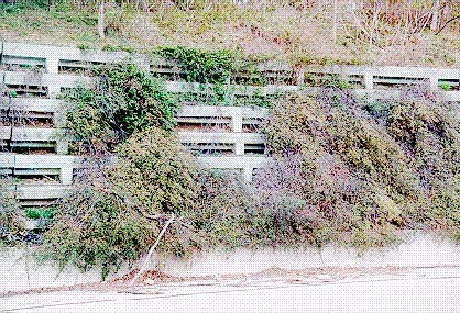
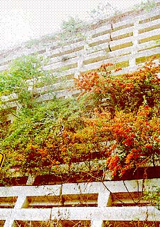
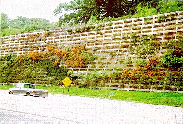
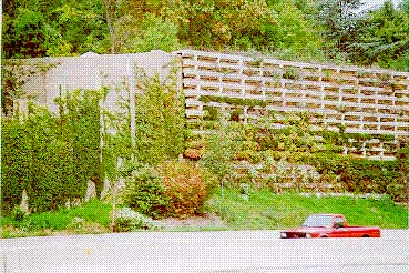
The objective of this research project was to evaluate the Evergreen Retaining Wall System regarding constructability, maintenance, planting treatments, acoustic properties and performance as a precast retaining wall. This system consists of precast concrete bin units of varying dimensions, stacked to conform to the required height. These stacked precast units are supported on a concrete footer. The erected units are filled with aggregate, and provide an open face that is filled with earth and vegetated with plantings in a variety of treatments.
The prime contractor on this project was Driscoll Construction Company, Inc. Excavation for the footer of the Evergreen Wall began on May 8, 1986 and was completed on May 21, 1986. This Class I excavation occurred concurrently with the general roadway excavation. Form work for the footer began on May 9, 1986 and was completed on June 8, 1986. Costs associated with this work included pouring the footer. See the lump sum breakdown for this item on page 11. Pouring of the footer began on May 12, 1986 and was completed on June 9, 1986. The pouring of the pedestals, which support the bottom course of the Evergreen units, began on May 22, 1986 and was completed on June 23, 1986.
The prime contractor on this project was G.A. & F.C. Wagman Inc. Excavation for the footer of the Evergreen Wall began on October 24, 1990 and was completed on May 3, 1991. This Class I excavation occurred concurrently with the general roadway excavation. Form work for the footer began on December 12,1990 and was completed on February 4, 1991. Costs associated with this work included pouring the footer are part of the lump sum breakdown for this structure, see page 9. Pouring of the footer and pedestals, which support the bottom course of the Evergreen units began on December 12, 1990 and was completed on April 4, 1991.
SR 476-300, BLUE ROUTE
NETHER PROVIDENCE TOWNSHIP, DELAWARE COUNTY
ENGINERING DISTRICT 6-0
Graphic
Evergreen Retaining Wall Typical Sections
Graphic
Typical Wall Precast Concrete Unit
(evergreen007-1.bmp--file was damaged)
Appendix A on page 26 contains the actual contract specifications for Section 100 used to construct the Evergreen Retaining Wall System. References to "U-Sections" within the specification refer to Sections within the Pennsylvania Department of Transportation's Publication 408 " Specifications". The Evergreen System was listed as a construction item in the construction projects listed below. The following information is related to total project bid costs and the costs bid for the Evergreen System by the three lowest bidders on these two road sections.
Appendix B on page 31 contains the actual contract specifications for Section 300 used to construct the Evergreen Retaining Wall System.
The fabrication, transportation, and erection of the Evergreen Wall System components proceeded in a smooth sequence with no major delays and on schedule.
Section 100
Major Maintenance Problems
* Weeds
* Handwork requirement for weeding
* Lack of moisture at the top of wall
* Insects/disease, e.g. spider mites on Cotoneaster
*
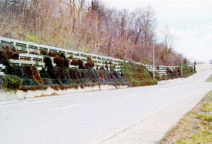
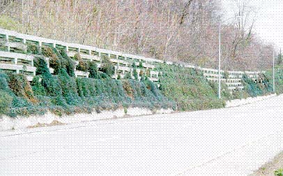
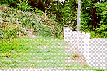
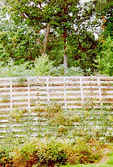
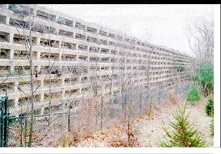
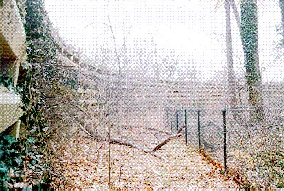
One of the primary reasons for constructing the Evergreen Wall System as opposed to a standard or other proprietary wall was to minimize disturbance of existing vegetation on the community side of the wall. The Evergreen Wall System was constructed in a manner consistent with this concept, and a strip of existing trees and vegetation has been retained as a buffer between the future highway and the adjacent community.
Graphic
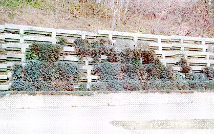
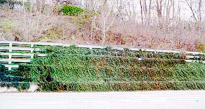
Graphic PHOTOGRAPHS, SECTION 100
Graphic
Graphic
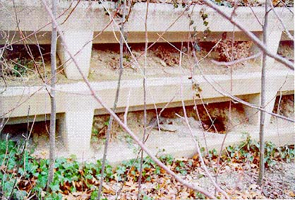
PHOTOGRAPHS, SECTION 100
Graphic
Graphic
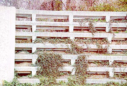
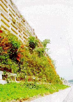
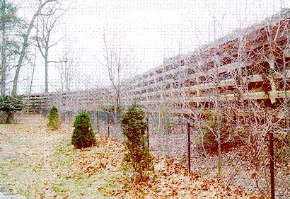
PHOTOGRAPHS, SECTION 300
Graphic
Graphic
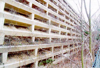
PHOTOGRAPHS, SECTION 300
Graphic
Graphic
PHOTOGRAPHS, SECTION 300
Graphic
Graphic
PHOTOGRAPHS, SECTION 300
Graphic
Graphic
PHOTOGRAPHS, SECTION 300
Graphic
Graphic
PHOTOGRAPHS, SECTION 300
Graphic
Graphic
PHOTOGRAPHS, SECTION 300
Graphic
Graphic
|
ITEM 2000-0016 EXPERIMENTAL RETAINING WALLS, S-16066
Description - This work is constructing an experimental retaining walls as indicated.
Materials - In accordance with Section 1001.2 and as herein specified.
Plantings - Section 808.
Reinforcement Bars - Section 709.1 and as follows:
Use Grade 60 deformed reinforcement bars. Billet, rail, or axle steel except No. 3 stirrup may be Grade 40.
Use epoxy coated reinforcement bars in traffic barrier.
Cement Concrete - Section 704 and as follows:
Use Class A Cement Concrete in footings and leveling pads.
Use Class AA Cement Concrete in traffic barrier.
Provide concrete for the precast modular units with a 28 day compressive strength of 5000 psi and an entrained air content of 5% in the plastic state with a tolerance of plus or minus 1.5%.
Construction - In accordance with Section 1001.3 and as indicated.
Do not Value Engineer the experimental retaining walls
Shop Drawings - Before fabrication, submit shop drawings for review and approval. Include layout plans, concrete footing dimensions, and reinforcement details; including design calculations, details of stepped installation on grades, material lists, and type of finish requirements. Include step-by-step erection instruction. Do not begin fabrication on the wall elements without the approved shop drawings.
Precast Units - Fabricate precast modular units in accordance with the approved shop drawings.
1) Tolerances: Provide minimum tolerance for the manufacture of units as follows: 2)
Face of panel, length or height = plus or minus 3/16 inch.
Deviation from square measurement of diagonal = 5/16 inch.
Location of reinforcement steel, cover tolerance - 1/4 to + 1/2 inch.
Otherwise within plus or minus 1/2 inch.
2) Forms: Construct forms of steel in a manner that will assure the production of uniform units, and leave them in place until they can be removed without damage to the unit.
3) Mixing and Placing Concrete: Proportion and mix as designed concrete mix in a batch mixer to produce a homogeneous concrete conforming to the specifications. For transporting, placing and compacting of concrete. Use methods that will prevent segregation of the concrete materials and the displacement of the steel reinforcement from its proper position in the form. Carefully place and vibrate the concrete in the forms sufficiently to produce a surface free from imperfections such as honeycomb, segregation or cracking. Use clear form oil from the same manufacturer through the casting operation.
4) Curing: Properly cure the units for a sufficient time so that the concrete will develop the specified compressive strength. 5)
6) Testing and Inspection: Acceptability of precast units will be determined on the basis of entrained air in concrete mixture, compression tests, and visual inspection. Furnish the facilities and perform all necessary sampling and testing in an expeditious and satisfactory manner. Acceptance will be as herein specified. 7)
8) Finish: Provide conventional surface finish, unless otherwise indicated.
Marking: Clearly scribe or paint with waterproof paint on the interior surface of each unit, the date of manufacture.
8) Handling, Storing, and Shipping: Handle, store and ship all units in such manner as to eliminate the danger of chipping, cracks, fractures, and excessive handling stress. 9)
9) Manufacture: Before shipment, examine all surfaces of precast elements. Properly patch all excessive voids and other defects of the exterior wall surfaces as directed. 10)
Do not ship the precast units before the required concrete strength is attained.
10) Acceptance: All materials used in manufacture of the precast elements including cement. Aggregates, water, admixtures, steel reinforcement, and galvanized metal items will be sampled and tested according to the standard procedures for these items. Do not fabricate until these materials have been approved. 11)
Fabrication of the precast elements is subject to random inspection. Make available for review results of tests required to be performed by the fabricator on the properties of the concrete mixtures and compressive strength.
Completed precast elements will be inspected before shipment and damaged or otherwise unsatisfactory elements will be rejected. Repair or replace to the satisfaction of the Engineer, any element damaged during handling, transporting, erecting, or backfilling.
Erection - Excavate as required, the foundation bed for the retaining wall and do not start erection before approval. If required or ordered, place granular backfill to the depth required under the footing, or leveling pad to replace unsuitable material.
Place bottom of footing below the prevailing frost depth with at least one foot cover over top of footing.
Construct cast-in-place footings with a 28-day compressive strength of 3000 psi, to the dimensions and details indicated at least 24 hours prior to placement of the wall units. Do not place wall units until concrete has attained a minimum compressive strength of 1400 psi.
Install precast concrete elements in accordance with the manufacturer s recommendations as shown on the shop drawings. Take special care in setting the bottom course of elements to the line and grade.
Do not exceed the allowable foundation bearing pressures indicated. Provide the footing or leveling pad so that no additional right-of-way is needed to accommodate the footing or leveling pad.
Consider the following for filling and backfill in sequence: first drainage, then filling, then backfilling, after erection of each element layer.
Have the fill material approved by the design engineer and the landscape architect or contractor for adequate material quality regarding plant growth and draining capabilities. Provide a fill material having internal friction angle of min. 30 degrees and that does not contain more than 40% passing a standard No. 200 sieve. Place the top soil material only at the outer front edge. Neither clay nor rocks bigger than 5 inch diameter are acceptable.
Check backfill material for proper friction angle according to design calculation. If worse than anticipated, a new design calculation and larger elements may be required. Do not use impermeable or wet material. Remove large blocks or chunks that could damage the elements.
Provide proper drainage as usual for retaining walls, preferably use perforated pipe in or behind bottom elements and add gravel or sand draining blanket or french drains behind wall or first element with gravel.
Fill in layers not exceeding 2 feet in fill and 1 foot in backfill.
Compact to not less than 90% Proctor (relative ASTM) density and not more than 95% respectively field CBR or CBR penetrometer 6%.
Do not drive within 6 feet of the wall with trucks or excavator.
Prevent loose intermediate earth fill and backfill material from getting wet and becoming waste by grading to slope and smooth roll in or plastic sheet covering.
Fill the interior of each successive course of precast modular units with fill material herein specified. Place backfill around the outside of the wall, as indicated or directed, in accordance with the requirements of Section 1001.3(t).
When erecting a battered wall. Place the backfill behind the wall to closely follow erection of successive courses of units.
Do not exceed 2 feet difference in elevations between the backfill and the top of the last erected course.
Make repairs at job site by experienced personnel utilizing methods and materials recommended by the manufacturer. Do patching only when conditions exist which assure that the repaired area will conform to the remainder of the work with respect to appearance, strength, and durability.
Furnish and install plantings in conjunction with the sound barrier walls as indicated and in accordance with Item 2000-0035 Landscaping for Experimental Retaining Walls.
Technical Support - Have a company representative at the project site to assist the fabricator, contractor and engineer until they are familiar and confident in casting, installation and construction procedures. Provide a technical representative to assist in the event unusual problems or special circumstances arise.
For information and technical assistance for the experimental retaining walls contact:
Evergreen Wall Systems
Clay Warner & Associates, Inc.
6069 Oakbrook Parkway
Norcross, Georgia 30093770 840-7069
Measurement and Payment - Lump Sum.
Payment for all landscaping for the Community Side Plantings is covered under Item 2000-0035
DESCRIPTION - This work is constructing an experimental, Evergreen Systems, Inc., retaining wall as indicated.
For information and technical assistance for the experimental evergreen retaining walls, contact:
Nitterhouse Concrete Products, Inc.
Box N
2688 Molly Pitcher Highway S
Chambersberg, Pa. 17201-0813
Attn: William Roemer (301) 771-4184
A. MATERIALS
Do not Value Engineer the experimental retaining walls.
Shop Drawings - Before fabrication, submit shop drawings for review and approval. Include layout plans, concrete footing dimensions, and reinforcement details; including design calculations, details of stepped installation on grades, material lists, and type of finish re5uirements. Include step-by-step erection Instruction. Do not begin fabrication on the wall elements without the approved shop drawings.
Precast Units - Fabricate precast modular units in accordance with the approved shop drawings.
1. Precast Evergreen Crib wall elements, end closure elements: Provide a concrete for the Precast elements with a minimum 28 day compressive strength of 5,000 psi and an entrained air content of 6% in the plastic state, within a tolerance of plus or minus 1.5%. 2.
Provide Cast-in-place parapets only. Use Class A Cement Concrete in footing and leveling pads.
(a) Use Grade 60 deformed reinforcement bars, billet, rail or axle steel except No. 3 stirrup may be Grade 40. (b)
(b) Tolerance: Provide minimum tolerance for the manufacture of elements as follows: (c)
Location of reinforcement steel, cover tolerance minus 1/4 to plus 1/2 inch. Otherwise within plus or minus 1/2 inch.
General dimensions, position of suspending devices within 1 inch; all other dimensions within 3/16 inch.
Element dimensions: Do not exceed dimensions as determined by length and transverse width near the legs by more than 1/2 inch.
Element surface finish: Do not allow surface defects on smooth formed surface, measured over a length of 5 feet by more than 1/4 inch in any direction.
Do not allow surface defects on exterior surfaces, measured over a length of 5 feet by more than 5/16 inch in any direction.
(c) Forms: Construct forms of steel in a manner that will assure the production of uniform elements, and leave them in place until they can be removed without damage to the element. (d)
(e) Mixing and Placing Concrete Proportion the mix as a designed concrete Mix in a batch mixer to produce a homogeneous concrete conforming to the specification. For transporting, placing and compacting of concrete, use methods that will prevent segregation of the concrete materials and the displacement of the steel reinforcement from its proper position in the form. Carefully place and vibrate the concrete in the forms sufficiently to produce a surface free from imperfections such as honeycomb, segregation, or cracking. Use clear form oil from the same manufacturer throughout the casting operation. (f)
(g) Curing: Properly cure the elements for a sufficient time so that the concrete will develop the specified compressive strength. (h)
(f) Testing and Inspection: Acceptability of the precast elements will be determined on the basis of entrained air in concrete mixture, compression tests and visual inspection. Furnish the facilities and perform all necessary sampling and testing in an expeditious and satisfactory manner. Acceptance will be as herein specified. (g)
(g) Finish: Provide conventional surface finish unless other wise indicated. (h)
(h) Marking: Clearly scribe or paint with waterproof paint on the interior surface of each element, the date of manufacture. (i)
(j) Handling, Storing and Shipping: Handle, store and ship all elements in such manner as to eliminate the danger of chipping, cracks, fractures and excessive handling stress. When in storage, support on firm blocking, to protect the exposed exterior finish and to prevent distortion. Do not ship the elements before the required 28 day concrete strength is attained. (k)
(j) Acceptance: Have all materials used in manufacture of the precast elements including cement, aggregates, water, admixtures, steel reinforcement and galvanized metal items sampled and tested according to the standard procedures for these items. Do not fabricate until these materials have been approved. (k)
Fabrication of the precast elements is subject to random inspection. Make available for review results of tests required to be performed by the fabricator on the properties of the Concrete mixtures and compressive strength.
Have the completed precast elements inspected before shipment. Damaged or otherwise unsatisfactory elements will be rejected. Repair or replace to the satisfaction of the Engineer, any element damaged during handling, transporting, erecting, or backfilling.
2. Fill Material Within Elements. 3.
(a) Provide granular fill material for inside the crib wall, free from organic and otherwise deleterious materials and conforming to following gradation limits as determined by AASHT0 T-27: Crushed or natural sand, Crushed or uncrushed gravel, blasted limestone, blasted sandstone or any standard size coarse aggregate meeting the following requirements. (b)
| Sieve size: | Percent passing: |
| 5 inches | 100% |
| No. 200 | 10-25% |
In addition, if the fraction finer than the No. 200 mesh sieve is between 10% and 25%, have the fill conform to the following requirements:
1. Do not exceed the Plasticity Index (P.I.) as determined by AASHT0 T-29 by more than 6. 2.
2. Do not exceed the fraction finer than 15 microns (0.0l5 mm) as determined by AASHT0 T-88 by more than 15%. 3.
3. Furnish material exhibiting an internal angle of friction of not less than 32 degrees for fines with zero cohesion as determined in a standard direct shear test (AASHT0 T-236) and have minimum moist density of 115 pcf, and the cohesion as determined by Standard Direct Shear or Triaxial Shear tests within the range of 50 to 150 psf. 4.
4. Maintain moisture content within + 2% of optimum. 5.
Provide top soil in accordance with Section 802 for filling of element front pockets to a depth of 4 to 6 inches.
(b) Backfill material Behind Crib wall. (c)
Furnish backfill material behind crib wall as indicated or directed in accordance with the requirements of Section 1001.3 (t). Backfill material within 1 foot behind crib wall is to be free draining granular material with a maximum size of 4 in. and not more than 8% passing No. 200 sieve.
Furnish to the Engineer a certification of compliance with the specifications.
Furnish a copy of all test results performed which are necessary to assure compliance with the specification.
B. WALL ERECTION
Technical Support - Have a company representative at the project site to assist the fabricator, contractor and Engineer, until they are familiar and confident in casting, installation, and construction procedures. Provide a technical representative to assist in the event unusual problems or special circumstances arise.
Grade level for the width necessary, prepare the foundation, as indicated and compact as directed. Remove and replace any foundation soil found to be unsuitable with granular material.
Place the bottom of footing below the prevailing frost depth with at least two feet cover over top of footing.
Construct cast-in-place footings to the dimensions and details indicated. Do not place the wall elements on the footings until the concrete has attained a minimum compressive strength of 2000 psi or has cured for at least 72 hours.
Handle and place precast elements and end closure elements in such a manner that they are not cracked or chipped and no damage is caused at seating areas. Place the elements in such a way that the final position is vertical or battered as indicated.
Install precast concrete elements in accordance with the manufacturer's recommendation as shown on the shop drawings. Take special care in setting the bottom course of elements to line and grade.
Have repairs at job site made by experienced personnel utilizing method and materials recommended by the manufacturer. Patch only when conditions exist which assures that the repaired area will conform to the remainder of the work with respect to appearance, strength and durability.
Fill the first element with 1 foot minimum of free draining material, as specified herein. Place fill material within the elements in layers of not more than one foot loose depth. Thoroughly compact using hand operated compaction machinery to at least 90% of density as determined by AASHTO T-99 at optimum moisture content. Simultaneously fill the front pockets of the elements with 4 to 6 inches of top soil, ensuring that it does not extend beyond front L-shaped section.
Place backfill around the outside of the wall as indicated or directed in accordance with the requirements of Section 1001.3(t) except place free draining granular material within
1 foot behind the crib wall as indicated herein.
Provide 2 ft. X 2 ft. pieces of geotextile fabric class 1 on the outer longitudinal beams at the joints to hinder erosion of the fill, if no other bridging of the gaps is specified on the drawings.
Closely follow erection of each successive course of elements with the fill and backfill operations. Do not exceed 2 feet difference in elevations between the backfill and the top of the last erected course.
Take care so as not to disturb the alignment of the elements during backfilling and compaction operations. Remove and replace any wall materials damaged during fill and backfill placement. Correct any misalignment or distortion of the wall elements caused by placement of backfill.
Provide uniform moisture content throughout each layer prior to and during compaction. Maintain the moisture content equal to or less than the optimum. Remove any backfill material which has a placed moisture content in excess of the optimum by 2% and rework until the moisture content is within the acceptable limit throughout the entire lift.
Perform compaction within 3 feet of the back faces of the elements with at least 3 passes of a lightweight mechanical tamper, roller or vibratory system. Decrease the lift thickness if necessary to obtain the specified density. Do not drive within 6 feet of the wall with truck or excavator.
At the end of each days operation, slope the last layer of backfill away from the wall in order to rapidly direct the runoff away from the wall face. Do not allow surface runoff from adjacent areas to enter the wall construction site. Backfill the areas behind and above the crib wall to the finished configuration indicated taking care to insure that the surface drainage is collected by interception ditches and diverted from flowing over the face of the wall. Eliminate erosive flow of surface water down, through and over the face of the wall.
Provide a continuous subsoil drain of 4 inches minimum diameter with a minimum fall of 1 in 50. Construct drainage outlets as indicated on the drainage details.
Tolerance of finished wall: Maintain the finished front face of the wall within the following tolerances:
| Variation in any one course | Not more than 1 inch variation from 1 foot straight edge |
| (2) Relative position of adjacent element in any one course in plan or elevation |
Within 1 inch of true alignment |
| (3) Variation in front batter | 1 inch in 10 feet slope from design slope |
| (4) Variation within batter slope | Not more than 1/2 inch from a 10 foot straight edge. |
| (5) Variation from plane surface along the wall. |
Not more than 1/2 inch from a 10 foot straight edge. |
| (6) Opening of gaps between elements |
2 inches except in curbed areas 4 inches |
Furnish and install plantings in accordance with the landscaping plans.
Perform all planting operations on the community side of the Evergreen Wall (both within and adjacent to the wall) during the planting season, immediately following the construction of each sound barrier wall.
MEASUREMENT AND PAYMEXT - Lump Sum
Plantings will be paid for separately
| Community Side |
Comments | |
| SHRUBS | ||
| Cotoneaster | 588 | 3" Pots |
| Blue Rug Juniper | 630 | 18" B & B |
| VINES |
||
| Baltic Ivy | 1848 | 15"-18" B & B |
| TOTAL LUMP SUM COST | $32,000 | |
| Community Side |
Highway Side |
Cost Each |
Subtotal Cost |
|
| SHRUBS | ||||
| Bush Cinquefoil | 271 | 242 | $10.00 | $5,130.00 |
| Cranberry Cotoneaster | 129 | 522 | $22.00 | $14,322.00 |
| Fire thorn (Laland) | 278 | 626 | $17.31 | $15,650.00 |
| Rock Cotoneaster | 254 | 113 | $22.00 | $8,074.00 |
| Rugosa Rose | 144 | 514 | $8.50 | $5,508.00 |
| Sargent Juniper | 309 | 211 | $19.00 | $9,880.00 |
| Tamarisk Juniper | 97 | 381 | $25.00 | $11,950.00 |
| GROUNDCOVERS | ||||
| Arronsbeard St. Johnswort | 814 | 922 | $12.00 | $20,832.00 |
| Lavendar Cotton | 374 | 357 | $7.50 | $5,482.50 |
| Memorial Rose | 274 | 304 | $7.50 | $4,335.00 |
| VINES | ||||
| Baltic English Ivy | 1082 | 1233 | $1.35 | $3,125.25 |
| Boston Ivy | 303 | 162 | $2.50 | $1,162.50 |
| Geranium Creeper | 353 | 422 | $5.50 | $4,262.50 |
| TOTAL COST | $109,713.75 | |||