MBTC 1057
PRE-DESIGNED TIMBER BRIDGES OF THREE TYPES FOR ARKANSAS COUNTY ROADS
PREPARED BY:
Dr. Larry G. Pleimann, Civil Engineering, University of Arkansas
Gregory R. Riley, Civil Engineering, University of Arkansas
FUNDED BY:
Mack-Blackwell Rural Transportation Center, University of Arkansas
Arkansas Highway and Transportation Department
Federal Highway Administration
June 2000
TABLE OF CONTENTS
Acknowledgments
Abstract
1.0 Introduction
2.0 Purpose and Scope
3.0 Literature Review
4.0 Background on Types of Timber Bridges
5.0 Bridge Design Computer Program
6.0 Timber Bridge Designs of Three Types
7.0 Conclusions and Recommendations
List of References
LIST OF FIGURES
Figure 1: National Interstate and State Bridge Data
Figure 2: National City/County/Township Bridge Data
Figure 3: Arkansas Interstate and State Bridge Data
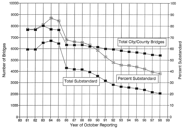
Figure 4: Arkansas City/County Bridge Data
Figure 5: Isometric Section of Solid Sawn Stringer Bridge
Figure 6: Isometric Section of Solid Sawn Stringers with Dowel Laminated Deck
Figure 7: Isometric Section with Glulam Stringers and Transverse Deck
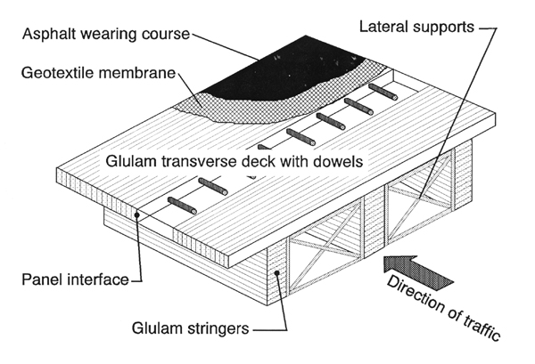
Figure 8: Isometric Section with Glulam Stringers and Doweled Transverse Deck
Figure 9: Isometric Section of Longitudinal Glulam or Dowel Laminated Deck
Figure 10: Isometric Section of Longitudinal Stress-laminated Deck
Figure 11: Isometric Section of Stress-laminated Deck Using Glulam Stringers
Figure 12: Cross-sections Used for Stress-laminated Box Girder Bridges
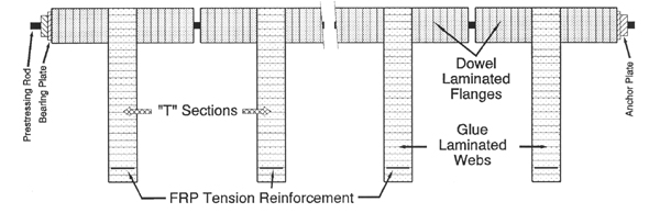
Figure 13: Cross-section of T-Beams with FRP Tension Reinforcement
LIST OF TABLES
Table 1: Published Bridge Data for the Fifty States and the District of Columbia
Table 2: Published Bridge Data for the State of Arkansas
Table 3: Responses to Questionnaire
Table 4: Type 1 Designs with 6 x 12 Stringers
Table 5: Type 1 Designs with 8 x 12 Stringers
Table 6: Type 1 Designs with 10 x 12 Stringers
Table 7: Type 1 Designs with 6 x 14 Stringers
Table 8: Type 1 Designs with 8 x 14 Stringers
Table 9: Type 1 Designs with 10 x 14 Stringers
Table 10: Type 2 Designs with 5 inch wide Glulam Stringers
Table 11: Type 2 Designs with 6.75 inch wide Glulam Stringers
Table 12: Type 2 Designs with 8.5 inch wide Glulam Stringers
Table 13: Type 2 Designs with 10.5 inch wide Glulam Stringers
Table 14: Type 3 Designs with 5 inch wide Glulam Stringers
Table 15: Type 3 Designs with 6.75 inch wide Glulam Stringers
Table 16: Type 3 Designs with 8.5 inch wide Glulam Stringers
Table 17: Type 3 Designs with 10.5 inch wide Glulam Stringers
ACKNOWLEDGMENTS
The author takes this opportunity to thank many people who have been of great help in accomplishing the work of this project and in producing this final report. These include three former graduate students, Mr. S. Grant Jordan who wrote the original version of PCBRIDGE, Mr. Lee R. Shaw who made some important improvements in the program, and Mr. Gregory R. Riley who used PCBRIDGE to do the designs listed herein and who drew all the pages of drawings and specifications [hard copies available upon request from MBTC].
ABSTRACT
The National Bridge Inventory every year lists the percentage of bridges in the United States under various jurisdictions that are "structurally deficient" or "functionally obsolete." That percentage is largest for "city/county/township" bridges. In recent years the two major causes for the rapid deterioration of those bridges with typical steel or concrete superstructures have been the use of deicer chemicals and the lack of adequate maintenance monies.
An alternative that could be of competitive cost and that could contribute to the economy of the state of Arkansas by further developing its timber industry would be the use of economical well-designed, well-constructed "modern" timber bridges for the replacement of sub-standard bridges on county and city roads.
A computer program written in 1991 was used to design a range of adequate simple span timber bridges of three different types with accompanying plans and guide specifications for them for ready use by Arkansas county road and bridge departments. The three types include 1) solid sawn stringers with transverse solid sawn deck planks, 2) glulam stringers with transverse glulam decks, and 3) stress-laminated full-span glulam stringers, all constructed of Southern Pine (SP).
This report contains tables of designs for the first type using six different SP stringer sections, for the second type using four different standard widths of SP glulam stringers, and for the third type using the same four separate widths of SP glulam stringers. The designs were done concentrating on flexural adequacy. The reader is guided through simple procedures so that the span length and/or the depth of the primary bending sections may be changed so that the designs may harmonize with any desired allowable deflection limitation, or desired smaller "load duration factor."
1.0 INTRODUCTION
1.1 Deterioration of the American Infrastructure
It is a commonplace currently to speak of the deterioration of the American
transportation infrastructure. The national media periodically have reports on
the crumbling of pavements that should have lasted much longer, or of bridge
failures caused by the combination of such deterioration and the lack of
adequate funding for maintenance within the separate jurisdictions responsible
for particular road and bridge systems. Some of these failures have led to loss
of life which demonstrated just how serious the problem is.
There are many sources for the deterioration of the U.S. public transportation systems. These include lack of maintenance because of a lack of adequate funding, heavier traffic volumes, and heavier loads particularly as truck traffic strives for increased efficiency by using larger axle loads and longer strings of trailers. In addition, certain environmental factors have effected a faster deterioration. Especially within the context of bridge and pavement maintenance, the increased use of deicing chemicals that began in the sixties has led to more rapid deterioration of reinforced concrete bridge decks and pavements.
The infiltration of chloride ions into the concrete causes the pH surrounding the reinforcing steel to become acidic. This change in pH allows the steel to oxidize. The resulting iron oxide crystals expand as much as 16 times the volume of the source steel [Crumpton, 1985]. The internal expansion produces high tensile stresses in the concrete. This leads to cracking near the top surface and spalling of the concrete follows. The direct exposure of the underlying reinforcement to the environment and traffic loads hastens the deterioration of the slab. Unless the damaged area is repaired, a significant loss of strength and/or service life of a pavement or deck will occur.
Most efforts to control the corrosion of deck and pavement reinforcement have been directed toward protection of the steel bars. Additional concrete cover, surface sealants for the concrete, corrosion inhibitors mixed with the concrete, reduced concrete permeability, cathodic protection, epoxy coating, and galvanizing are examples. The use of fusion epoxy coated bars has become standard in the effort to protect concrete reinforcing steel from corrosion, certainly in the state of Arkansas. However, epoxy coating may not be the final answer since small cracks in the coating may hasten local corrosion [Clear, 1992]. Epoxy coating is also being used with pavement dowel bars. Few other alternatives have been proposed for the protection of steel reinforcement apart from the suggestion of using more expensive stainless steel [Black, et al, 1988], or to search for another more effective coating.
An alternate effort has attempted the development of other forms of reinforcement that are not susceptible to corrosion. Fiber reinforced polymer (FRP) bars provide one such option. This "composite" material consists of thin high-strength synthetic fibers embedded within a hardened polymer matrix. FRP bars have already been used for slabs on grade, as prestressing tendons [Preis and Bell, 1987; Nanni, 1991], in marine environment structures, and in structures wherein non-magnetic properties are important such as magnetic resonance imaging installations [Roll, 1991], and large transformer foundation pads. The bars are not susceptible to corrosion and have high tensile strength.
The attention of the nation was brought vividly to focus on the problem of bridge deterioration in 1967. The Silver Bridge over the Ohio River between Kanauga, Ohio and Pt. Pleasant, West Virginia failed under afternoon rush hour traffic. The bridge was a 40 year old steel suspension bridge of a total length of 1750 feet. It had been inspected as recently as April of 1965. But on that day it was ready to fail and let 75 cars and trucks fall into the river, killing some 46 people. Later investigation showed that the combination of a lack of adequate maintenance and the use of deicer chemicals had led to the rapid deterioration of the main suspension "cables." However, they weren't cables per se, but eyebar links that are often susceptible to deterioration and fatigue fracture.
The Silver Bridge failure led directly to the establishment of the Federal Bridge Inspection program. Working through the state departments of transportation, the program instituted an inspection survey that intended initially to increase the frequency of inspections so that every federal, state, and smaller local jurisdiction bridges would be inspected at least once every two years. The results of this inspection were to be included in a national data base, or bridge inventory system. In Arkansas, the Arkansas Highway and Transportation Department (AHTD) has worked to increase the inspection frequency, especially for those bridges whose condition is problematic. Some bridges are inspected every year if not more often.
This federal inspection program led to the common usage of phrases such as "structurally deficient" and/or "functionally obsolete." The results of the annual inspections are kept in a national bridge inventory and are published periodically. The author first noticed a typical summary of results in an annual November issue of Better Roads magazine which began to publish such data in 1978. In the 1989 issue, for example, of the some 588 thousand bridges in the fifty states and the District of Columbia, a little over 38 percent, 225 thousand, were still "structurally deficient" and/or "functionally obsolete." Of that number, almost exactly two-thirds, 151 thousand, were on rural highways or city streets, off the federally funded system.
Tables 1 and 2 below summarize the results of the Better Roads data for the entire nation and for the state of Arkansas from the year when essentially all the states reported complete results for their jurisdiction until the present. The following Figures 1 through 4 present the same data in a graphical format.
|
Reporting Year |
|
|
|
|
|
|
|
|
|
|
|
|
|
|
|
|
|
|
|
|
|
|
|
|
|
|
|
|
|
|
|
|
|
|
|
|
|
|
|
|
|
|
|
|
|
|
|
|
|
|
|
|
|
|
|
|
|
|
|
|
|
|
|
|
|
|
|
|
|
|
|
|
|
|
|
|
|
|
|
|
|
|
|
|
|
|
|
|
|
|
|
|
|
|
|
|
|
|
|
|
|
|
|
|
|
|
|
|
|
|
|
|
|
|
|
|
|
|
|
|
|
|
|
|
|
|
|
|
|
|
|
|
|
|
|
|
|
|
|
|
|
|
|
|
|
|
|
|
|
|
|
|
|
|
|
|
|
|
|
|
|
|
|
|
|
|
|
|
|
|
|
|
|
|
|
|
|
|
|
|
|
|
|
|
|
|
|
|
|
|
|
|
|
|
|
|
|
|
|
|
|
|
|
|
|
|
|
|
Reporting Year |
|
|
|
|
|
|
|
|
|
|
|
|
|
|
|
|
|
|
|
|
|
|
|
|
|
|
|
|
|
|
|
|
|
|
|
|
|
|
|
|
|
|
|
|
|
|
|
|
|
|
|
|
|
|
|
|
|
|
|
|
|
|
|
|
|
|
|
|
|
|
|
|
|
|
|
|
|
|
|
|
|
|
|
|
|
|
|
|
|
|
|
|
|
|
|
|
|
|
|
|
|
|
|
|
|
|
|
|
|
|
|
|
|
|
|
|
|
|
|
|
|
|
|
|
|
|
|
|
|
|
|
|
|
|
|
|
|
|
|
|
|
|
|
|
|
|
|
|
|
|
|
|
|
|
|
|
|
|
|
|
|
|
|
|
|
|
|
|
|
|
|
|
|
|
|
|
|
|
|
|
|
|
|
|
|
|
|
|
|
|
|
|
|
|
|
|
|
|
|
|
|
|
|
|
|
|
|
FIGURE 1: National Interstate and State Bridge Data
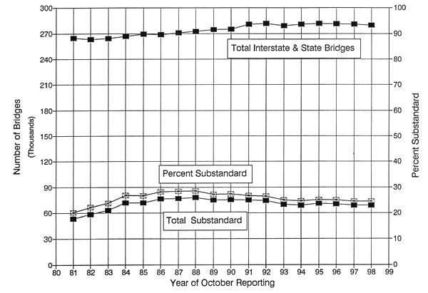
FIGURE 2: National City/County/Township Bridge Data
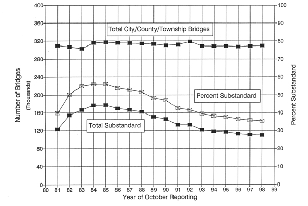
FIGURE 3: Arkansas Interstate and State Bridge Data
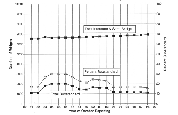
FIGURE 4: Arkansas City/County Bridge Data
Each figure plots a total number of bridges from 1981 through to the present, the total number substandard in that category, and the percent substandard for that category. A cursory examination of Figures 1 and 3 for Interstate and State Bridges for the nation and for Arkansas leads one to the same conclusions. The total number of bridges in this category seems relatively stable, but with some decided increase as the general network of roads is enlarged and upgraded. The percent of those national bridges that are substandard is relatively low in both cases, but far higher than they should be. Fortunately, the percent substandard of Interstate and State Bridges is lower in Arkansas than the national average, and the last decade has shown a consistent decrease in that percentage both at the national and Arkansas levels. In Arkansas during that time period the rate of decrease has been even more pronounced. When attention is focused on a problem, and the seriousness and importance of the problem is understood, the American people respond. Arkansans are a particularly self-reliant and practical people, and it is not surprising that they have responded in a more intense fashion.
Consideration of the corresponding Figures 2 and 4 for "City/County/Township" Bridges at the national level and for Arkansas is even more dramatic, and, in places, puzzling. First, in both cases, the absolute numbers of substandard bridges and the corresponding percentages are much higher than for the Interstate and State bridges. This is understandable for a variety of reasons. The bridges of the Interstate system and many of the bridges on U.S. highways within the separate states are part of a newer system. Also, the federal government has typically more power to tax for maintenance monies than the individual states, especially if the state is predominantly rural and less affluent. The obverse of such a situation is that the "state-aid" bridges, as they are called in Arkansas, are less well funded. In times of financial distress the first item to be neglected is maintenance and so the bridges suffer. Also, the audience for a substandard bridge on the Interstate and state system is larger since the daily traffic count on these bridges is typically larger. The larger audience can bring much more political pressure for repairs than say the small population of a poor county concerned with a local bridge. Despite these factors, the changes in the "City/County/Township" category have been dramatic both at the national and Arkansas levels. At the national level, after a peak in 1984, there has been a steady reduction in the absolute number and percentage of substandard bridges. The same trend is evident in the Arkansas "City/County" bridge data but the reduction is even more dramatic. The peak value is again in 1984, but the percent substandard is 86.8. By 1998 percent substandard has been brought to a much lower value, 37.9, but that is still higher than the national average for this category, 35.4 percent. Arkansas has made major improvement in its state-aid bridges, but still has a way to go to catch up with the nation in this category.
Some of the data is curious for the state of Arkansas. The total number of bridges in the City/County system has also been dropping. One major reason for this may be the increased popularity in substituting systems of multiple culverts for bridges. It could be interesting in the future to do a more detailed study of the history of the changes in Arkansas's off-federal-jurisdiction bridges. Despite the dramatic reduction in the absolute number of Arkansas' substandard state-aid bridges, the reduction of its percentage substandard for the same category is not as pronounced.
1.2 Timber as an Alternative
Part of the motivation for this study is the conviction that timber, as a
bridge structural material, can make a significant contribution to bridge
replacement needs in the United States, particularly for shorter span bridges in
the "City/County/Township" jurisdictions. The other part of the motivation is
the recognition that this conviction is not widely shared by many people both in
and out of the bridge engineering community.
The first ways for humans to cross streams were either to ford them at shallow points, or to make use of convenient exposed stones in the stream bed. Perhaps the use of a naturally fallen tree inspired our ancestors to intentionally fell trees for similar use. Later masonry arches were also used. It has been the author's experience in teaching structural design of both masonry and timber, that the two materials, although the oldest and most natural of structural materials, are also the least understood and the most maligned. Actually, because they are both natural materials they are, therefore, more random in their behavior, more difficult to model mathematically, and more complicated than either steel and/or reinforced concrete. This complexity has delayed the development of their adequate and complete "engineering." Their lesser strength, when not adequately "engineered," has led to a poor reputation for both materials.
Nevertheless, the early history of bridges in the world and in the United States is a history of the use of timber as a structural material. The effort to recall these long lasting and previous successes has become a project for the timber industry. The reader is directed to the first two chapters of Mike Ritter's Timber Bridges: Design, Construction, Inspection, and Maintenance [Ritter, 1990]. Another good example is a recent article in the magazine Public Roads [Duwadi and Ritter, 1997] that traces the history of timber bridges from the beginnings of the United States to the present, and describes the development of the technologies of lamination and pressure treatment that are the basis of "modern" timber bridges, and the source of the current competitiveness of timber with other bridge structural materials.
Despite the major technological developments in the latter half of the twentieth century with respect to timber bridges, there is still a basic current mind-set in the bridge design community against the use of timber as a bridge structural material. Ritter [1990, p. 1-19] offers his own explanation to that hesitancy. "Perhaps the biggest obstacle to the acceptance and the use of timber has been a persistent lack of understanding related to design and performance of the material." Ritter, in turn, quotes Johnson [1986] as to the causes of this "lack of understanding."
The timber industry is one of those industries that has not made a substantial unified effort to generate and distribute technical information. This has been interpreted by some engineers as a reflection on the suitability of the material itself, and not as an indictment of the industry for failing to provide the information. The reason the timber industry has not met the challenge is quite obvious once one looks at the respective industries.
Johnson goes on to say that whereas the steel and cement industries have both separately and, on occasion, together actively promoted structural steel and reinforced concrete as structural bridge materials, the multiple parts of the timber industry have not.
That is a dated statement, because in 1989, under the auspices of the Department of Agriculture's U.S. Forest Service, the National Timber Bridge Initiative Program was established, domiciled at their Northeastern Area office in Morgantown, West Virginia. The project is now called the National Wood in Transportation Program. Part of the program is a competitive cost sharing arrangement for encouraging the design and construction of innovative demonstration timber bridge projects, with an annual national budget that varies each year, but is in the order of 1.0 to 1.5 millions dollars.
Each state of the Union has received benefits from the program. The author has been shown several such bridge projects in Arkansas. He also witnessed and filmed the installation of an innovative bridge project in Washington County. That bridge was a "stress laminated box girder" structure that incorporated all of the current lamination developments in timber structural materials. The timber bridge initiative program was been the source of a number of significant solutions to local bridge replacement needs across the United States, but it has not caused a major revision of attitude toward timber bridges.
Another part of the Forest Service's information strategy was a series of timber bridge design conferences. The author has attended several of these conferences. He remembers vividly the opening address at one such conference held in Birmingham, Alabama. The speaker was the then Secretary of State for Alabama, a man who was also a licensed professional civil engineer. His primary point was that the potential economic advantage of the use of timber bridges for his state was two-fold. On the one hand they promised a relatively cheap solution to the problem of replacing substandard spans on Alabama rural roads. On the other hand they gave promise to promoting the growth of the important timber industry of his state. The increased use of timber bridges has an identical two-fold potential for the state of Arkansas. The sections for the Washington County stress-laminated box girder timber bridge mentioned earlier had been manufactured of mixed oak from Southern Illinois. They could just as well have been manufactured by and contributed to the economy of northwest Arkansas.
It would be a mistake, however, to think that this mutually contributive economic solution is without problems. At this writing the onset of global warming is being taken with increased seriousness. The world weather is being threatened by the most significant El Nino of several decades. A five hundred year flood in North Dakota and southern Canada was been preceeded by numerous summers of hundred year floods throughout the world. The contribution of forests in exchanging oxygen for carbon dioxide becomes exceedingly important. The conflict between human use that can be made of forest products as fuel, paper, structural material, and raw material for the chemical industry has to be balanced with values provided by forests remaining intact, i.e., flood protection, erosion control, wildlife habitat, oxygen manufacture, soil humus, and human recreation. Even intense reforestation is not necessarily an answer if the method of it defies the need for biodiversity in the forest. Obviously, this is an area needing the wisest of human decisions, and the ability to compromise on goals that include values that are not just short-sighted immediate human values. Trade-offs are inevitable, but the author is still of the belief that the use of well-engineered and constructed timber bridges will have some significant part to play in the real solution of Arkansas' rural bridge replacement needs.
1.3 Timber Bridges in Arkansas
The common American mind-set that views the design of timber bridges as a
waste of money is widespread in Arkansas as well. It is the author's experience
and opinion that this is true not only among the general public but also at all
echelons of the bridge design-construction- maintenance community as well.
This negative mind-set does not have as significant a discouraging effect on creativity and flexibility in the "Interstate and State" system, because the public is accustomed to seeing steel stringers under concrete decks for most major bridges and overpasses on the Interstate, federal, and state highways of Arkansas. Timber superstructures could be a viable option for many of these bridge structures. But the bridge design section of the AHTD has honed the design of concrete-deck-over-steel-stringers bridges to the point that it is very easy and therefore very economical for the AHTD to continue their use for both short and long spans. Nevertheless, there is some flexibility emerging in the bridge department of the AHTD that is probably caused as much as anything by the need to modify designs in terms of life-cycle costs instead of initial construction costs. The issue of bridge superstructure and deck deterioration plays a large role in these changes.
Several years ago the author attended a one-day short course sponsored jointly by the AHTD, and the "Arkansas Area Prestressed Concrete Council." The latter was at that time a new organization unknown to the author. The membership of the organization consists of precast prestressed concrete element producers who are interested in the potential Arkansas market. The vast majority of the Council's members are domiciled in states bordering Arkansas because there are very few such producers inside the borders of Arkansas. The primary selling point of the conference was the superior durability performance of precast stringers as described in a presentation given by a staff member of the Portland Cement Association (PCA) [Rabbat, 1993]. The address was a comparative study of the durability of certain types of bridge superstructures using data taken from the National Bridge Inventory. The primary point of the article was that bridges with prestressed concrete stringers were longer lasting. The structural material with the poorest record in the study was timber. The author's own reaction to this was that the development of the technology that underlies "modern" timber bridges is so relatively new and seldom used that one could believe that the study was not a fair comparison with respect to timber.
The author in previous years kept lists provided by the AHTD of the distribution of various structural materials for the superstructures of state-aid bridges in Arkansas. His recollection is that approximately half of the superstructures of those bridges in an era about a decade ago were made of timber.
Negative reaction to the decay of traditional timber bridges has led many county judges and their road and bridge departments to make a commitment to find inexpensive alternatives to timber bridges. Used railroad flatbeds have been used. These were cheap at first, but their price has risen with their popularity. They are difficult to "load rate" because their strength reduction due to previous fatigue loading is not easy to evaluate. Moreover, sometimes they are "modified" in an unsafe manner in order to be fitted to a particular bridge site. Also, corrosion of these all-steel superstructures is not easy to prevent.
Another popular program for some counties has been the use of side-by-side precast concrete channel sections for use in various span lengths for county bridge replacements. The author is not certain when these plans were developed. The copies he has for both the bridge sections and the plans for the forms list the University of Arkansas Division of Agriculture Cooperative Extention Service in the title block. He believes, however, that the design of the sections was developed initially by AHTD for the sake of state-aid bridges in the mid-60's. Several counties in the state made early use of these plans and have produced the sections for their own bridge replacement program for quite some time. Washington County is an example of such early use. Craighead County, with Jonesboro as County Seat, and Jefferson County, with Pine Bluff as County Seat, have newer and more advanced production facilities for year round production of the channel sections.
The plans allow varying standard lengths of 19, 25, and 31 feet, depending on whether the main girder reinforcement consists of #9, #10, or #11 rebars respectively. Most counties with which the author is familiar use a 30 foot span length and #11 rebars. Seven of the 3'-7.5" wide channel sections side by side provide sufficient width for two standard lanes and space for precast curb units at the two outside edges.
Counties that use this system have found it very economical. Some other counties purchase similar units from a few precast manufacturers in the state. All in all, this has been a very useful and successful program for short span bridge replacement on counties in the state.
The scope for this project will be described in more detail later. The initially intended scope included surveying some 21 counties in the southern third of the state for help in identifying bridge sites where economic comparison could be made of alternate bridge replacement schemes including as many as three types of timber superstructure bridges. The response to a questionnaire sent by the author to the county judges in those 21 counties was so discouraging in terms of the positive response to the use of timber bridge superstructures yet so interesting as to the variety of types of bridges systems used, that the author decided finally to send the questionnaire to all 75 of the counties in the state. Table 3 following gives the results of the questionnaire in tabular form. The questionnaire was modified twice as the early responses indicated difficulties the counties experienced in understanding the intent of some of the questions. The three separate versions of the one-page questionnaire sent to the county judges appear in the Appendix. If blanks occur in Table 3 it is because the person responding from the individual county did not include a response to that question. Three lines in the table are completely blank because the county judge and/or road and bridge department director chose not to respond not only to the initial mailing but to as many as three follow-up mailings. All this is indicative of busy schedules, but the responses (or lack thereof) also indicate a general disinterest in timber as a bridge superstructure material. Nevertheless, that 72 counties out of 75 eventually responded makes the answers useful.
yes (p)
One of the primary interests of the author was whether counties had made a
conscious policy decision to not use timber as a superstructure material.
Sixty-four of the 72 questionnaires received responded to this question. The 32
"YES" responses are indicated in similar bold capitals in the
table. Thirty-two responded "no," but this may be misleading because most of
them were making a concerted effort to replace their bridges by some means other
than timber superstructures. Of the eight counties that returned a questionnaire
but did not respond to this question only two indicated that they had not made
use of wood in the past, but six were using alternate types for their standard
method of bridge replacement presently. Although at one time about half of the
"state-aid" bridges in Arkansas had timber superstructures, no county responding
is using any type of timber bridge as its preferred method of bridge
replacement. That would indicate a majority disenchantment with timber
presently. Fifty-nine counties responded to the question regarding the use of solid sawn
stringers. Thirty-one of them admitted to using solid sawn timber stringers at
one time or another. The author believes that many of the 28 who responded "no"
to that question were thinking of recent use. But only two counties of the 52
responding had ever used laminated preconstructed stringers or decks, one of the
many applications and techniques that we would now include as part of a "modern"
timber bridge. One wonders if the remaining twenty did not reply to the question
because they did not know what a "glulam timber beam" was. Forty-eight of the 64 counties giving a response to the question said that
they had used railroad flat cars as bridge superstructures. Such use is a recent
development and not easily forgotten. The seeming economy of such use has
obviously been very convincing. Also, forty counties of 64 responding said they
had made use of precast reinforced concrete bridge sections, and 10 said that
they had manufactured the units themselves. Interestingly, although the most
typical form of bridge superstructure on the interstates and federal highways
are steel stringers acting in composite fashion with a cast concrete deck, only
30 of the 58 counties that responded to that question had ever used this method
on county roads. Three counties responded that they used timber decks over steel
stringers and one modified the question to the use of reinforced concrete
stringers. Many counties indicated they they were interested in replacing deteriorated
short span bridges by single or multiple culverts. The preferred culvert
materials included plain and galvanized steel, and plastic lined pipe. A few
used tank car sections. Some used precast reinforced concrete sections. As many
as three indicated the possible use of treated timber culverts, which would
certainly be an option, especially if the streams contained elements corrosive
to the other alternatives. Relatively few responsed with their preferred material for pilings. Most that
did included either cast-in-place or precast reinforced concrete piles or steel
I-shapes. Only eight indicated that timber piles were used routinely. All in all, the responses given were only somewhat surprising to the author.
The lack of understanding of "modern" timber construction as a viable
alternative again seemed to mirror the general lack of knowledge of the public
with respect to technological alternatives including treated timber. But it is
obvious that counties are actively searching amidst new technology to find some
alternative bridge replacement technique that fits their budget, the level of
training and capabilities of their crews, and their actual bridge site
conditions. Despite the current lack of interest in timber as a superstructure material
for short span bridge replacement, it is the conviction of the author that
timber bridges are a viable alternative. Obviously the demonstration of their
viability rests in the hands of those organizations and industries that are
intimately connected to and knowledgable of this alternative. It is probably a
matter of time before their potential may be known and realized. In the
meantime, continued progress can be made in developing further improvements in
timber bridges. For example, consider the recent development of fiber composite
reinforced glulam stringers that adds significantly to the moment carrying
capacity of a typical glulam cross section. Such research should be continued in
those universities equiped for it. It is hoped that this publication may add to
the interest and use of at least the three types of timber bridge
superstructures chosen for inclusion in this study.
ARKANSAS
ASHLEY
BAXTER
BENTON
BOONE
BRADLEY
CALHOUN
CARROLL
CHICOT
CLARK
timber
deck
CLAY
CLEBURNE
CLEVELAND
COLUMBIA
CONWAY
CRAIGHEAD
CRAWFORD
CRITTENDEN
CROSS
DALLAS
DESHA
DREW
FAULKNER
FRANKLIN
FULTON
GARLAND
GRANT
GREENE
HEMPSTEAD
HOT
SPRING
HOWARD
INDEPENDENCE
IZARD
JACKSON
JEFFERSON
JOHNSON
LAFAYETTE
LAWRENCE
LEE
LINCOLN
LITTLE
RIVER
LOGAN
LONOKE
MADISON
MARION
MILLER
MISSISSIPPI
MONROE
MONTGOVERY
NEVADA
NEWTON
OUACHITA
PERRY
PHILLIPS
PIKE
POINSETT
POLK
POPE
PRAIRIE
PULASKI
RANDOLPH
SALINE
SCOTT
SEARCY
SEBASTIAN
SEVIER
SHARP
ST. FRANCIS
STONE
UNION
VAN BUREN
WASHINGTON
WHITE
WOODRUFF
YELL
2.0 PURPOSE AND SCOPE
2.1 Project Purpose
The previous chapter sought to justify this project by setting it in the general context of the
current need of repair of the nation's infrastructure. Although the notion of using timber as the
structural material for short span bridge replacement in the state of Arkansas is not popular,
nevertheless it could very well be the wisest decision for certain actual spans and sites. A major
aid for counties in deciding on the use of a particular timber bridge type would be the development
of standardized designs that could be easily adapted to specific sites, and could be quickly
provided by timber suppliers and/or glulam manufacturers.
This idea is consistent with the current status of timber bridge design and the intentions of the timber industry. The accomplishments of the National Timber Bridge Initiative and continued improvement in the technology of timber bridge construction has renewed interest in some quarters in using modern timber bridges to replace many structurally deficient short span bridges on county roads. In a recent joint publication of the U.S. Forest Service and the U.S. DOT FHwA, Development of a Six-Year Research Needs Assessment for Timber Transportation Structures [1992], the twentieth highest priority of 118 total needs was to "develop prefabricated, modular timber bridge systems that are easily transported."
One of the basic assumptions for such bridges in the state of Arkansas would be that the material used would be Southern Pine. It is the dominant structural timber species for the Southeastern United States and is, therefore, readily available. Moreover, it has certain other distinct advantages over other structural softwoods. Southern Pine is a very strong and dense material yet it also has a physiology that makes it more amenable to pressure treatment with wood preservatives. The proportions of lateral "rays" that allow the deep penetration of treatment fluids into the body of the wood are larger in Southern Pine than they are in say Douglas Fir. This physical property makes the potential durability of properly designed, treated, and constructed Southern Pine timber bridges longer than would normally be the case.
Part of the emphasis of the project was to simply the design and construction of timber bridges as much as possible. In some states, such as Iowa, the head of a county road and bridge department is required to be a registered professional engineer. That is not the case in the state of Arkansas. The people of Arkansas have fewer high school diplomas per thousand than most other states, let alone university degrees. The heads of the road and bridge departments are more often than not experienced persons of high intelligence and capability, but their training has been by experience rather than formal education. Therefore, although they can adequately construct a bridge they may not have been trained to understand the structural principles that underlie those construction procedures. Sometimes the lack of formal training may inhibit the vision of the departments to try something new. Sometimes the same lack may allow risky procedures vis-à-vis some popular new trend. Therefore, the emphasis in this project has been on the use of simple designs that can be easily adopted by county crews, designs which can be easily constructed.
This emphasis on ease of construction and simplicity can best be achieved by standardization and "preconstruction." By standardization is meant limiting the number of types of bridges being designed and planned to a small number. The initial and final intention was only three types, although one of the final types were different from that initially intended. Using more than one type would provide a wider range of span lengths, more than the ranges inherent in say the use of the precast reinforced concrete channel-sections previously described.
By "preconstruction" was meant the notion of that all timber suppliers and glulam manufacturers would have access to the same set of standardized plans. If the program were to gain popularity then some of the elements could be pre-manufactured and be waiting in storage for a quick response to a county's needs. This feature was later reconsidered since it would not be currently advantageous economically for the timber suppliers and/or glulam manufacturers to "stockpile" sections. And the time necessary for site and foundation preparation at a particular site would usually be sufficient for the preparation of the elements by the supplier including pressure treatment.
The actual design of the bridge sections made use of a computer program written and revised a few years previous to this project. The program was written originally to design seven different types of timber bridges. As part of this project the program was revised for the second time to bring it up to date with the most recent LRFD edition of the AASHTO bridge design manual [1994] and the American Forest and Paper Association's National Design Specification for Wood Construction [1991] wherever the latter superseded the former.
2.2 Scope of the Project
The immediate focus of this research was the improvement of Arkansas' rural bridges by
developing a series of standard designs for timber bridges that could easily be used to replace
county bridges that were "functionally obsolete" and/or "structurally deficient." Therefore, it had
primarily to do with rural highways.
The tasks associated with this project were initially planned to include the following steps in essentially the order listed, although there was much overlapping of effort.
Literature search for the most recent improvements in the design procedures of modern timber bridges. This would include background in the most recent changes in AASHTO design procedures for timber bridges and the AFPA's NDS.
Updating and improvement in the existing computer program to incorporate any necessary changes.
Consultation with glulam and solid sawn timber producers and pressure treaters in the southern half of Arkansas regarding grades and sizes of timber readily available, their particular pricing structures including transport, etc.
Consultations with four counties in the southern part of the southeastern half of the state. A site needing bridge replacement conformable to either a single span or a series of short spans would be selected in each county for comparitive designs.
Development of standard designs for three types of timber bridges with accompanying plans.
Economic study of the relative costs, both immediate and long-term, among the four sites with respect to possible preconstructed timber bridges, the use of commercially available concrete channels, and the usual methods of bridge construction in the counties.
Report writing and organizing of meetings of interested parties for discussion of the results.
The three types of timber bridges originally to be included in the project included: solid sawn stringers under a transverse plank deck, glulam stringers under transverse glulam deck elements, and longitudinal glulam deck elements. All of these timber bridge superstructure systems have been proven in their applicability. As the proposal was examined by federal authorities the author was urged to include the use of a stress-laminated system. The author was initially hesitant to use stress-lamination technology because it added a significant level of sophistication in construction procedures for the county bridge crews. However, the use of glulam sections that stretched from one abutment to the other rather than the use of individual solid-sawn segments of partial length solved the problem. In the fourth chapter a description of each of these types will be given both graphically and by text within the context of the historical development of lamination techniques.
With respect to tasks numbered 4) and 6) it was obvious that the lack of interest shown by most county road and bridge departments for this project meant that the author chose to eliminate those tasks. They could well be the subject of a later larger study that would seek to document and examine the economic effects of the bridge replacement choices of counties throughout the state of Arkansas.
Since there was little interest in timber superstructure bridges among the counties it will probably be of little use to insist on the organization of "meetings of interested parties" as mentioned in the task numbered 7) until such time as that interest demonstrates itself.
3.0 LITERATURE REVIEW
Masonry and timber are our most ancient of structural materials. They have been essentially replaced as our major structural materials by structural steel and reinforced concrete from the middle of the 19th century when portland cement concrete was invented and in subsequent years as stronger steels replaced iron both as rolled structural shapes and as reinforcement for concrete. In the meantime, both older materials continued to be used primarily for small scale construction, and their design was more an art than a science. Both masonry and timber are natural materials. The resulting random nature of the materials delayed the development of appropriate engineering principles for their structural design. As natural materials they are much more complex in behavior. Therefore, they were to some extent misunderstood and only recently has the engineering community developed or is in the process of developing increasingly adequate design procedures for both materials.
In the modern period between the beginnings of the industrial revolution in Europe and the development of structural steel and reinforced concrete as we know it our society made use of timber and masonry for many sophistocated structures. One illustration of this was the use of masonry and timber for major bridges in this country. This use is well documented in the Ritter chapter [1990] and the Public Roads article [Duwadi and Ritter, 1997] mentioned earlier. These documents at one and the same time illustrate technology that we need to relearn, and point to recent movements in the direction of remembering and reapplying that technology.
The loss of the previous technology and the use of poor practice in the design, treatment, and construction of timber bridges in the early decades of this century led to the use of timber bridges that gained a reputation for lack of durability. The address by Basile Rabbat [1993] previously cited enjoyed pointing to the use of prestressed concrete stringers as the most durable design for bridges. His article also listed timber bridges as the least durable. All of this has contributed to the negative mind-set vis-à-vis the use of timber as a structural material for bridge superstructures descibed in Chapter 1.
Recent improvements in the technology of "modern" timber bridges has in turn lead to the development of increasingly sophisticated timber design codes. This includes primarily both the National Design Specification for Wood Construction [AFPA, 1991] with its supplemental Design Values for Wood Construction, and the LRFD Bridge Design Specifications [AASHTO, 1994]. The former publication is also moving in the direction of an LRFD design format with the publication of the Load & Resistance Factor Design Manual for Engineered Wood Construction [AFPA, 1996].
Any university trained engineer knows that one does not learn primarily from codes. Unfortunately lack of interest in timber design in the mid-half of this century meant that there were relatively few textbooks available in timber design. When the author was an undergraduate at LSU in the mid-fifties he had an opportunity to study timber design only because his undergraduate instructor in structural steel design elected to teach his class timber design in the structural steel design lab until such time as the class had learned enough steel design procedures to have something to design. We used what was then the only text available, the fourth edition [1954] of Scofield and O'Brien's Modern Timber Engineering, published by the Southern Pine Association. By the fifth edition [1963] it was in the hands of Dr. William A. Oliver of the University of Illinois. As Dr. Oliver retired the revision and development of the text was given to Dr. German Gurfinkel of the University of Illinois. Under his direction this text reached a second edition [1973] as Wood Engineering. It was for a number of years subsidized by the then Southern Forest Products Association, but has since gone out of print. Chapter 9 of that edition contains much on the "Design of Wood Bridges" that is still of value to the interested engineer. In the meantime, recent years have seen the development of several new timber design textbooks. Currently in its third edition is Donald Breyer's Design of Wood Structures [1993], probably the most complete and thorough timber design text, although it contains no material specifically pointed toward the problem of timber bridge design.
Another recently introduced text is Structural Design in Wood, now in its second edition [1997], by Stalnaker and Harris. This text introduces the reader to LRFD design of timber structures but has only a few sections on bridge design in Chapter 15. The only other text available is Somayaji's Structural Wood Design published in 1990. It essentially has no material related to timber bridge design.
Besides textbooks there are also publications of real value that are more closely related to timber trade organizations. Most recently this includes the second edition [1995] of Faherty and Williamson's Wood Engineering and Construction Handbook. This is a very practical book with clear recommendations regarding construction usage of timber members. It contains a significant section on timber bridges written by Ritter.
The American Institute of Timber Construction is primarily associated with glulam materials. It publishes a Timber Construction Manual. The fourth edition [1994] of the manual contains a good section on timber bridge design.
The Forest Products Laboratory of the U.S. Forest Service located in Madison, Wisconsin publishes many research and performance reports on timber bridges. In addition it distributes a periodic listing of related publications from other sources that are germane to timber construction which it offers for free to its readership for the asking.
As the author and his graduate assistant were well under way with the work of this project the author discovered two important publications available from the U.S.F.S. F.P.L. publications service. At first glance they seemed to negate the need for this project. The first is a set of plans entitled Standard Plans for Southern Pine Bridges [Lee, Ritter, Triche]. The author considered abandoning the project when he discovered this publication. However, the project was continued because the author felt that county work crews in Arkansas could profit more from simpler designs and from different types of bridges. One of the three types of timber bridges reported in this project is completely different from any of the three types of the FPL plans, i.e., the use of glulam stringers and transverse glulam deck sections. It had been intended to not use stress-lamination technology in this report, but federal authorities strongly suggested the practice. So, one of our three types makes use of continuous glulam stringers stress-laminated side-by-side to form an orthotropic deck. It was thought that this kind of design would give Arkansas county work crews less problems than sawn lumber stress-laminated decks with non-continuous pieces. The third type of bridge construction is the same in this report as in the FPL publication. That type consists of solid sawn longitudinal stringers covered with transverse solid sawn deck planks. Much of the design, configuration, hardware usage is just as the author was introduced to it by Dr. Trische at a timber bridge design conference at Birmingham, Alabama several years ago. The excellence of Dr. Trische's approach was apparent then and strongly influenced the author.
In both of the types which we have used that mirror the uses of the FPL publication there are also many differences in design properties and standards as well as final design dimensions. Again, the effort has been made to make this more appropriate to the Arkansas county construction context.
The other FPL publication that appeared after the present project was well under way is Plans for Crash-Tested Bridge Railings for Longitudinal Wood Decks [Ritter, Faller, Lee, Rosson, Duwadi]. The separate publication of this set of plans from the previously mentioned FPL plan set is symptomatic of what to do with the issue of whether or not the side railing of the bridge must be designed by methods that have been verified by crash tests. Whether such railings are required on a bridge is often an issue of whether the funding of the bridge contains federal monies. We had already elected to draw the plans for our three sets of bridges using the same sort of corrogated metal railing and give the county the option of whether to use it or not. If a crash tested railing is required we would suggest the county consult the FPL plan set for alternatives.
In formulating our designs with the three types of bridges we began with the timber bridge design software that had previously been developed. We then upgraded it for consistence with Mr. Ritter's suggestions [1990], and with respect to the latest AFPA's NDS and with AASHTO's LRFD design procedures.
4.0 BACKGROUND ON TYPES OF TIMBER BRIDGES
The computer program used in this project mirrors the historical sequence of development in short span simply-supported timber bridges. The earliest kinds used are still usable with proper design, construction and maintenance. From the earliest to the most recent types, the movement has been a matter of trying to make the spans longer, and more durable, as the loads also increased. Doing so required the development of pressure treatment of the wood against its natural enemies, and also the development of several forms of lamination so that small pieces of wood could be made to act as a single composite. The computer program in its current form includes the design of nine separate types of simply-supported single span bridges.
One-way pan joists framing into collecting girders that then deliver vertical reaction loads to columns in reinforced concrete floor construction were initiated because they echoed the "post and beam" methods of timber building construction. Similarly, the earliest forms of timber bridge construction harkened back to intentionally felling trees across streams to allow easy crossing from one side to another. Even today, typically on isolated forest roads, logs will be felled, debarked, lashed together, and covered with a surface course to function as simple bridges. Our discussion will begin with a more sophisticated later imitation, the use of solid sawn stringers with a plank deck spanning across them.
All such bridges and subsequent types use elements that are in a horizontal position and which are subjected to vertical transverse gravity loads. Therefore, they are essentially beams. Typically numerous such beams are set parallel to one another to fill out the necessary width of the roadway. A complication comes from the loads being localized to tire footprints. As a beam ("stringer") deflects under the pressure of a wheel immediately above it the loaded stringer by virtue of the transverse connecting bridge construction between the stringers causes the unloaded stringers at either side to deflect also, thus sharing the applied load to some measure among all the stringers. Thus what is often viewed initially as a "1-dimensional" behavior of a beam is more often a "2-dimensional," or "orthotropic," plate type of behavior. The way in which this lateral sharing of load is played out is different in each type of bridge system.
4.1 Historical Sequence of Bridge Type Development
The early modification of the "lashed log" type of construction took the form of solid sawn
stringers with a series of transverse plank deck members as shown in Figure 5 below.
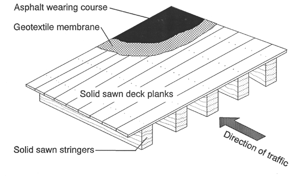
The deck planks are relatively shallow but have to carry a moment effect if the wheel load is between stringers and applied directly to the planks. This requires more stringers since the span of the shallow planks must be kept small. In the effort to spread the stringers further apart and need fewer stringers the first form of lamination was invented. The deck pieces were turned on edge and initially nailed one to another. This was known as nail lamination. At first the planks were nailed in sequence in the field throughout the length of the span. Later the deck was done in modular widths. Also a procedure was developed so that deck sections could be prefabri-cated in uniform widths in a shop situation using presses to embed larger diameter connectors in a staggered triangular pattern. This "dowel laminated" deck is shown in Figure 6 below.
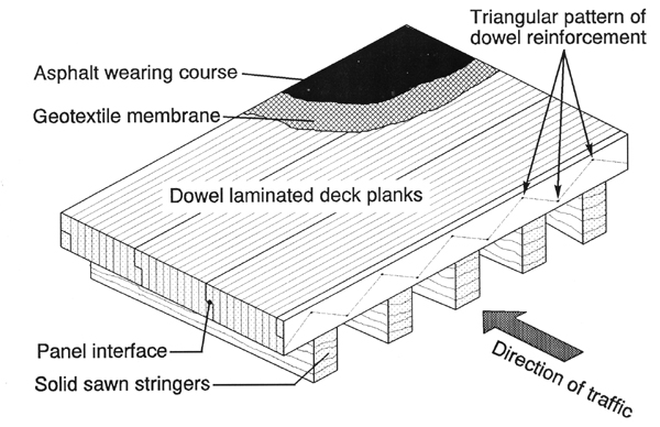
Note the overlapping of the transverse sections by means of "half depth" planks added to each edge of the modular transverse sections.
The use of flexurally stronger decks and the need for longer spans led to the use of stringers that incorporated the next development of lamination in both the deck sections and in the stringers themselves. The method of lamination used was glue laminated timber, known briefly as "glulam." The transverse decks were again made in modular widths and the stringers were made in standard widths, but the number of laminations ("lams") were selected to give the depth needed for the flexural strength of the stringers for a given span. Again the materials could now be used in as efficient a manner as possible. Application to bridge building required the development of water resistant glues for this form of lamination as well as progress in the development of pressure treatment. The individual lams are often treated with water borne salts. This type of treatment does not inhibit the gluing process. After the individual members for the bridge, both stringers and transverse deck sections, are constructed they can be sent to the treatment plant for a second treatment with creosote or pentachlorophenol. The use of glulam stringers and deck sections is illustrated in the Figure 7 below.
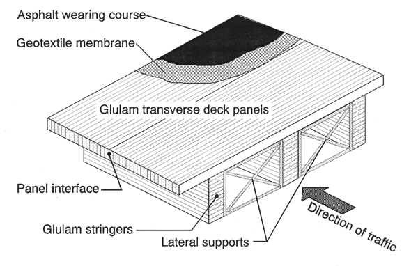
Because the stringers can become quite deep and yet remain rather narrow as one tries to decrease the number of stringers while increasing the span, there is now the need for the inclusion of lateral supports between the stringers at a spacing along the stringers sufficiently close to defend against lateral torsional buckling. This can be achieved by either a steel frame, as indicated in the figure, or by the use of shorter lengths of the same dimensional cross section as the stringers. The latter would be analogous to "blocking" between floor joists. The former steel frames are easier to install and lighter in weight and thus facilitate construction.
Another issue introduced by the use of glulam transverse deck panels side by side is the problem of "shear" or "wheel load" transfer between panels. As a wheel load moves forward to the edge of a panel that panel is depressed on one side of the panel interface and the panel ahead of it is not. Therefore, it is desirable to find a way to lock the deflection of the two adjacent panels together. One common method of doing so is illustrated in the following Figure 8. For the dowels to do the job of shear transfer they must be large enough, embedded in the glulam panels with sufficient tightness, and spaced as closely as needed. Unfortunately, when these three conditions are successfully achieved construction problems arise in aligning the holes in two adjacent interfaces and being able to pull one of the panels snugly against one that has been previously placed. For these reasons some users of this type of bridge have ceased using the doweled procedure in favor of the method of the previous Figure 7, i.e., simply placing the premanufactured panels side by side and securing them underneath to the stringers they cross. This still leaves the problem of shear transfer, but it is lessened by the support provided by the top of the stringer as two adjacent panels cross it. There are other procedures that can be achieved in supplying shear transfer at the bottom of the interface. In this project it was decided to not use the dowels for shear transfer.
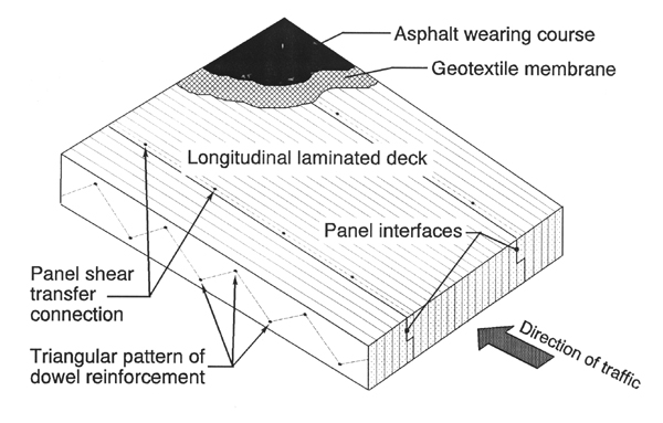
Even when shear transfer is provided problems occur that may be partially avoided by the use of the combination of a geotextile membrane and asphalt wearing course as illustrated in all the bridge type figures. Differential vertical movement between the interfaces of any deck elements results in "reflective cracking" at the road surface. But this is alleviated by the presence of this surfacing combination and is recommended for all types of timber bridges.
Improvements in the procedures for lamination and the influence of many reinforced concrete bridges consisting of a longitudinal constant thickness deck led to the notion of longitudinal nail laminated decks and longitudinal glulam decks. These two types of bridges are illustrated in the following Figure 9. The transverse bending coming from the two-dimensional lateral orthotropic action of the deck is not as well resisted by these methods of lamination. These types of bridges have been used successfully in the United States, but subsequent improvements have kept such longitudinal glulam or longitudinal nail-laminated decks from becoming widely popular.
The next logical form of lamination to be introduced was that of the stress-laminated deck. It was initially introduced in Canada as a method of strengthening existing longitudinal decks. Horizontal channel sections were added at both outer vertical edges of the existing deck with the back of the channel snugly against the edge. The depth of the channel was such so as to allow the placement of transverse horizontal high-strength prestressing rods across both the top and bottom surfaces of the longitudinal panels. The rods were then prestressed so as to introduce lateral pressures between the timber sections thus adding to the transverse orthotropic strength of the total bridge and, therefore, the longitudinal strength as well. The same principle was then applied to new construction by prestressing through pre-drilled holes at the mid-depth of the pieces that would become the longitudinal deck. This type of bridge is shown in Figure 10 below.
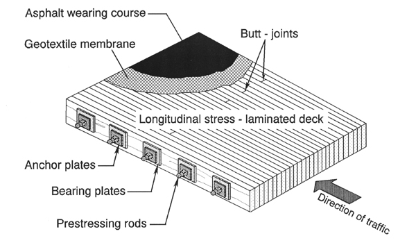
On occasion channel sections have been used extending the full length of the deck, but the more common arrangement is the one shown with individual anchor and bearing plates. This is economical as is the use of solid sawn unsurfaced timber pieces saving finishing and lamination costs. It also allows the use of hardwood segments as well as softwood. Because the individual solid sawn segments are of limited length, the segments are butted against one another within each individual section line. At these butt-joints the full bending capacity of the timber cross-section cannot be developed. Hence there is some loss of flexural efficiency in this method.
Moreover, the deck is typically delivered to the job in full span length panel segments whose width is roughly a half lane. On the job site the segments are assembled side-by-side into full lane width segments while maintaining the full camber the segments had when delivered to the job. The joined segments are then lifted into place and the lane-wide segments are then attached laterally.
The procedure for this lateral attachment is fairly complicated, involving the release of the prestressing in every other rod. These untensioned rods are connected by threaded sleeves with those of the next lane-wide element and retensioned. Then the process is repeated with the other half of the prestressing rods that had been in tension during the first lateral attachment. Half of the rods, at the minimum, being under tension at all times maintains the camber in the sections and gives sufficient flexural strength to support both the dead weight of the bridge panels and the personnel and equipment of the joining process.
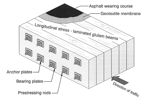
It was the opinion of the author that the previously described procedure could easily lead to problems if the county work crew was not totally familiar with the process. Therefore, the last type of bridge type decided on included the use of glulam sections to be placed side-by-side spanning from one abutment to the other before they would be stress-laminated together through pre-drilled holes. This would allow even longer spans and a much easier construction process. This type of bridge is illustrated in Figure 11 below. The increased depth of the glulam beams may well require the use of two or more levels of prestressing rods. But such multiple levels are common enough in other variations of the use of these types of construction.
In the meantime continued development has resulted from the creative application of all the previously developed technology. Many of these types hold promise of even more economical use of timber bridges and the achievment of longer span lengths for significant loads. The Figure 12 below, for example illustrates two types of preconstruction sections for assembling stress-laminated box girder bridges. A sample of the upper type exists in Washington County of Northwest Arkansas as an example of the National Timber Bridge Initiative. The section consists of primarily "I" shaped sections spanning the full length between abutments. The webs are full depth glue laminated sections to which flanges have been added on both sides by means of dowel lamination. The bridge edges are "closed in" by means of "C" shaped sections at both sides. These have dowel-laminated flanges on only one side. Once all the sections are in place the prestressing rods are pulled through predrilled holes in the flanges and upper and lower webs, anchored on both ends, and pulled to the proper tensile force. The sections in the figures are schematically separated to illustrate the passage of the continuous rods through the entire bridge width. As is true in any use of stress-lamination, this tension force will have to be checked and re-established later because the presence of some creep in the wood will lessen the prestressing force. Box girders are an economical use of timber materials.
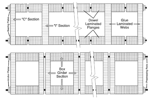
The second type of box girder assembly procedure is a set of side-by-side "box" sections. These are easier to construct, and there is less likelihood of damaging the sections in this form. The author has observed the construction of a simply-supported bridge of the first type. The sections were raised by straps extending under the bottom flanges of the sections. Lifting in this manner tended to cause curvature in the lower flanges with some subsequent misalignment of the holes for the prestressing rods. The author recommends the use of lifting rods in the top surfaces of the glulam webs to alleviate this problem. Neither the "C" and "I" type nor the "Box" section type of box girder bridges were recommended for this study because of the potential for construction error.
A final variation and most recent development is illustrated in Figure 13 below. If flanges are added to the glulam webs at the top only the sections become T-beams that have their own particular strength. In recent months this T-Beam strength has been added to by the "reinforcement" of the bottom tension zone of the webs by the placement of Fiber Reinforced Polymer (FRP) layers at a "glue line" near the bottom of the web. This is a proprietary patented process and such T-Beams are manufactured by a private industry.
4.2 Computer Program Scope and Bridge Types Used
The primary principles that governed the decision as to the types of simply-supported
timber bridges to be used in this project were 1) simplicity of construction and installation, and
2) the desire for a full range of span lengths as might be desired by any particular county. The
maximum span length is governed by the length of member that may be carried by highway
transportation. The three types decided on were:
- Solid Sawn Stringers With Solid Sawn Transverse Deck Planks:
This type of bridge is the oldest type in terms of historical development. It is a type with which most road and bridge crews have experience. It can be built to last, and the materials are readily available. It would provide an acceptable type for short span bridges. - Glulam Stringers With Transverse Glulam Decks Without Shear Transfer Dowels:
There is wide experience across the country with the erection of this type of bridge. Arkansas county road and bridge crews could learn this erection procedure easily. Steel frame sections were selected for lateral supports guarding against lateral torsional buckling. The glulam sections are easily manufactured by Arkansas industry, and this type would provide an adequate solution for intermediate span lengths that could be combined with the other two types for longer or shorter spans. - Full Span Glulam Stringers Stress-Laminated To A Longitudinal Deck:
With some instruction and experience the erection of this type of deck could be easily mastered by county road and bridge crews. The basic materials are easily manufactured and pressure treated by Arkansas industry. The use of full span sections would make erection and stress lamination that much easier. And this type could solve the need for relatively longer spans for any particular location.
The computer program used in this project to develop standard designs of all the three types listed above will be described in more detail below. It was written initially to design bridges of eight types excluding the last of the three types decided on for this project. Its second revision added that third type. At present it does not include the design of box girder or T-beam sections that use all three types of lamination illustrated in Figures 12 and 13 above.
4.3 Meetings with Industry Representatives
Even though final decisions had been made with respect to which three types of timber
bridges were to be designed there was still a wide range of variables that needed clarification and
decision before design could continue. These included optimum sizes to use for the solid sawn
stringers and transverse planks, and for the glulam stringer and transverse deck sections. In
addition to sizes there remained the need to know the most readily available best grades of
Southern Pine for use in the solid sawn sections and in both the horizontally and vertically
laminated glulam sections. These grade decisions would also decide the allowable stresses that
would be used in the design processes.
To help make these decisions the author and his graduate assistant made two visits to respected producers of timber products in the state of Arkansas. The first visit was a full afternoon of talks and plant observation at Unit Structures, Inc. of Magnolia, Arkansas on July 18, 1996. The company is a division of what was once the Koppers Corporation, but it is a division that concentrates on the production of glulam sections. Our chief contact was Mr. Harry Smith, then Senior Structural Engineer, but we had a good discussion with senior managerial staff including Mr. James H. Madden, Vice President of Engineering.
One of the most interesting aspects to the meeting was the almost unanimous opinion expressed on the part of the engineering and production staff of the company that the intent of this project was to some extent futile, especially in the state of Arkansas, because of the bad reputation of older wooden structures, the unfamiliarity of the Arkansas engineering community with the advantages of "modern" timber bridges, and the reticence of most Arkansas county road and bridge departments to try something new, particularly in wood.
Nevertheless, the Unit Structures personnel were willing to share their opinion of the optimum widths, grade options, lamination combinations and resulting allowable stresses for both horizontally and vertically laminated timber. In the case of the former they recommended visually graded Southern Pine in the lamination combination 24F-V3 giving allowable stresses of 2400 psi for Fb, 200 [240] psi for Fv, 650 [740] psi for Fc, and 1.7 [1.8] x 106 psi for E. These allowable stresses have been changed somewhat in the most recent 1997 AFPA NDS Supplement. Those changes are indicated in brackets in the above listing of allowable stresses behind those from the 1991 NDS Supplement. The results in this study come from the use of the 1991 values. The use of the most recent values should make little difference in the results since the bending stress was not changed and that stress would normally control the section size and span. The change in modulus of elasticity would make some small inversely proportional changes in deflection calculations. The use of the 1991 values would predict larger less conservative deflections. It should also be noted that the Forest Products Laboratory designs [Lee, Ritter, Triche, 1995] should match in the third bridge type since they also used the visually graded Southern Pine 24F-V3 lamination combination.
The Unit Structures personnel also suggested economical widths of 5 and 6.75 inches for the stringers combined with transverse glulam decks as well as for the width of the side-by-side full-span stringers that would be stress laminated together in the third type of bridge. Other suggested allowable widths for stringers in the second bridge type so as to optimize the number and spacing of the girders for longer intermediate spans were 3, 8.5 and 10.5 inches.
For the latter vertical orientation of the laminations that would be used as the transverse decks in the second bridge types, they again recommended visually graded Southern Pine in the same 24F-V3 lamination combination but now in horizontal lamination. This meant allowable stresses in the transverse glulam deck sections of 1600 psi for Fb, 175 [210] psi for Fv, 560 psi for Fc, and 1.6 x 10⁶ psi for E. Again there was only a slight difference in the 1997 NDS Supplement (indicated in the bracketed value) that would affect only shear strength. The vertical thickness of the transverse glulam deck panels were recommended at 5 inches minimum.
The second visit was an almost full day with Mr. Robert ("Bob") Moore on July 23, 1996. Mr. Moore is the manager of Commercial Lumber Sales, Inc. and River City Bridge, domiciled at the same location on Bay Oaks Drive in North Little Rock, Arkansas. Mr. Moore is a supplier of large solid sawn treated sections, and through the second organization has built numerous creative simple span timber bridges using solid sawn stringers. Several of his installations were partially funded through the Timber Bridge Initiative program.
For the stringers in the first bridge type Mr. Moore recommended the use of visually graded Southern Pine with a grade of No. 2 or better which would normally be kiln dried to a moisture content of 15%. The project elected to use the No. 2 SR grade, recognizing that any available "better" grade would be stronger and more conservative than the designs listed in the report and on the plans assuming the No. 2 rating.
The values given in the NDS Supplement for Southern Pine timbers (Table 4D) assume wet service conditions and the appropriate "wet service (adjustment) factors" were divided into these stresses to give the assumed dry condition allowable stress values used in the program and listed below. The design program was constructed so that wet or dry service conditions would be inputed for both the stringers and/or the transverse planks. This procedure gave assumed "dry" design allowable stresses of 1100 [850] psi for Fbs (single use), 1265 [977.5] psi for Fbr (repetitive use), 95 [100] psi for Fv, 526.5 psi for Fc, and 1.4 [1.2] x 106 psi for E. The 1997 NDS Supplement changes to the 1991 values are listed in brackets behind the 1991 values. The use of the 1997 values would be less conservative than the use of the 1991 values both in bending capacity of the section, and deflection values. This report chose to use the original 1991 NDS supplement values. Future use of the software could modify these results.
Mr. Moore also recommended transverse solid sawn plank dimensions of 3x8 or 3x10 inches in the first bridge type and a range of stringer cross section dimensions varying from 4 by 8 inches to 8 by 12 inches for optimum prices. The project chose to use a 3x10 transverse plank dimension, and a range of stringer dimensions from 6x12 through 10x14. The aforementioned set of Southern Pine plans by the Forest Products Laboratory personnel assumed No. 1 Dense SR, and No. 2 SR grades with equal or higher allowable bending stresses. So, all things else being equal, the designs in the present study would result in slightly shorter spans.
The 3 x 10 inch sections used as the transverse planks would technically qualify as solid sawn dimensional lumber. The No. 2 SR grade (assuming dry service conditions) listed for visually graded Southern Pine dimensional lumber (Table 4B) gives 1260 psi for Fb, 90 psi for Fv, 565 psi for Fc, and 1.6 x 10⁶ psi for E. There were no changes from these values in the 1997 NDS Supplement. The bending stress value, Fb, has been multiplied by the "flat use" adjustment factor, Cfu, of 1.2 since the planks will be oriented with the 10 inch dimension horizontal.
The use of these allowable stresses and cross section dimensions in the design of the three bridge types is given in the two following chapters.
5.0 BRIDGE DESIGN COMPUTER PROGRAM
The design of the three types of bridges presented in this report used a computer program finished initially in July, 1991. It has been revised twice since and its structure and use is described in the pages below. It would normally be available from the author on 3.5" floppy disk. However, the current use of increasingly sophisticated versions of Windows and their included versions of MSDOS has made it virtually impossible to run the PCBRIDGE program and its sub-programs. It will be advantageous as well as necessary in the future to rewrite the program in Visual Basic.
5.1 Sequence of the Development of the Computer Program
The program used to design the three types of simply-supported timber bridges used in
this project was written in Microsoft's GW-BASIC, version 3.22. The bridge design program,
PCBRIDGE, has a more general application and was developed over a period of some nine years.
It was the main work of Mr. S. Grant Jordan who finished his master's degree in early July of
1991. Another graduate student, Mr. Lee R. Shaw, made improvements in the program and
brought it up to date in the Spring of 1994. The idea for the present project came later, and a
third graduate student, Mr. Gregory R. Riley, made other improvements and then used the
program to produce tables of predesigned bridges of the three types described previously.
The intent of this project was to provide Arkansas county road and bridge departments with some encouragement and guidance in making decisions as to best type of timber bridge among the three with respect to their particular site locations and span needs. The plans give an initial idea as to the probable sizes and the configuration of the parts of the bridge, and how to make some economic decisions through material volume estimates that are included in the program and in the published results. As necessary the program shows a disclaimer that directs the user to have any plans for a particular bridge evaluated, confirmed and stamped by a registered professional engineer. But that engineer should also be able to receive guidance from the program and the accompanying plans.
Accompanying this report is a set of drawings in an 11" x 17" format for quick access by the user. The plans summarize the essentials of this report, include all necessary details and drawings, relevant references and appropriate standards and specifications.
5.2 General Structure of the Computer Program
After the program PCBRIDGE has been installed and started two introductory screens will
appear. Sequencing through the screens requires only the pressing of "any key to continue." The
third screen is used to select the type of simply-supported timber bridge to be designed from a list
of nine types. A facsimile of that screen appears below.
MAIN MENU
|
The symbol "==" above represents a flashing cursor. Typing the appropriate number and striking the "Enter" key loads and begins the specific sub-program for the design of the selected type of bridge. The following describes the sequence of screens and required input for types "1," "4," and "9" from the menu above, which are the three types selected for design in the project. What follows in this chapter is the sequence of screens in sub-programs associated with each of the chosen types as used in the most recently operative DOS based version.
5.2.1 Screen Sequence in Designing Type 1, Solid Sawn Stringers and Transverse Plank Deck. The screen descriptions will be in text rather than as facsimiles. The attempt is made to describe both the appearance of the screen and the range of options available in entering alternate data values. The screens are listed in their order of appearance.
- This screen lists the default strength parameters (allowable stresses in psi) for the
solid sawn stringers. The default species and grade is visually graded Southern
Pine No. 2 SR together with all the corresponding allowable stresses listed in
section 4.3 above. The species and any or all of the seven stress parameters can
be changed at the discretion of the user.
- The second screen shows similar information for the transverse solid sawn deck
elements. The allowable stress values are different from those for the stringer
sections. The same range of changes are allowed.<
- The third screen affords the user a choice in assuming wet service conditions, wet
or dry, for both the deck and stringers separately. Choosing a "wet" service
condition applies the appropriate "wet service" adjustment factor to each of the
allowable stresses. The typical decisions in this project were to choose a "wet"
condition for the deck members, and a "dry" condition for the supporting
stringers, assuming that the asphalt wearing surface and the underlying geotextile
layer together with the underlying transverse deck would protect the lower
stringers from saturation. Studies in the future examining the protection from
those uppermost layers as well as the use of oil bourne pressure treatment might
reasonably allow use of a "dry" assumption for the deck as well as the stringers.
- The fourth screen requests entry of the span length in feet, and the bridge width in feet. The typical entry in this project was 24 feet for the bridge width. This would be standard for a typical two-lane bridge. Following those entrys the program states a default loading of an AASHTO HS20-44 truck and asks if the user wishes to change it. If the user wishes to make a change, he/she is then offered a choice of HS20-44 (again), HS15-44, H20-44, H15-44 or OTHER. Choosing "OTHER" allows the user to define his/her own truck loading by specifying in pounds the tractor front and rear axle loads, the rear trailer axle load, and the distance in feet between the rear tractor and trailer axles.
It is at this juncture that control is shifted from PCBRIDGE to the sub-program SOLPLANK which designs the first type of bridge. Values for the allowable stresses, span, width of roadway, and loading are carried forward into this sub-program. We will now continue our description of the screen sequence with no change in numbering.
- The next screen cautions the user that he/she needs to be ready to input a number
of parameters and indicates the current default values. The first is a decision as to
whether the dimensions for the stringers and deck sections are for "solid sawn"
or "S4S." The next is the size of the deck plank sections, followed by the stringer
sections. Finally, the default value for the average thickness of the asphalt wearing
course is given. The last line asks "Y/N" whether the user is ready to enter the
above values. The obvious answer is "Y" but if the user chooses "N" control is
sent back to PCBRIDGE to the first screen that asked for allowable stresses.
Assuming the user entered "Y" . . .
- The next screen displays the previously selected span, roadway width and loading
at the top. Below it asks for a choice of stringer finish using "1" for solid sawn,
and "2" for surfaced sections for the stringers and then the same choices and
indicators are given for the deck members.
- The next two screens continue the same display of previously selected values at the
top. Below it first displays the current deck section default dimensions and asks
for agreement or changes.
- Next it displays in a following screen the current
stringer default section dimensions and again asks agreement or for changes.
- The next screen continues the same top display. It notes that the current default
with respect to lateral stability is two restraints at the ends only of the simply
supported stringers and asks for the number of additional lateral restraints that the
user wants to specify.
- The next screen continues the same top display. It repeats the default average
asphalt wearing course thickness as well as the corresponding crown and edge
thicknesses and asks for any change in the average wearing course thickness.
- The next screen is the most complex thus far in the program and gives the present
results for the design of the stringers. Since the stringer cross section dimensions
were previously chosen the design basically has decided the minimum number
necessary and the spacing between them. This has been selected so as not to
exceed the flexural strength of the transverse deck sections.
The upper part of the screen contains two columns. The left hand group repeats the previous decisions as to deck thickness, stringer cross section dimensions, and average asphalt wearing course thickness. The right hand group gives in pounds per foot of span length the deck dead load, the stringer dead load, and the asphalt dead load. Just below the last item is the current stringer center-to-center spacing.
The bottom portion of the screen is divided into four zones. Each reports the adequacy of the current design of the stringers with respect to either bending, deflection, lateral stability, or shear. Below each reporting is a statement as to the adequacy illustrated in green if the design is adequate and red if it is not. The upper left hand area reports the "design" bending stress and the "actual" bending stress in the stringers. The upper right hand compares the calculated live load deflection versus the allowable deflection and indicates acceptability. The lower left hand area compares the "design" lateral stress versus the "actual" and the lower right hand compares the "design" shear stress with the "actual" stress. At the very bottom of the screen is the request to "hit any key to continue."
- The next screen is essentially the same as number (11) except that now the focus
is on the adequacy of the deck design. The same entered and calculated
dimensions and dead loads are given at the top, and the bottom is arranged now in
three regions displaying both allowable and actual stresses for bending and shear
of the deck sections, together with green or red statements as to adequacy or code
disallowance. The third region lists the number of lateral supports selected for the
stringers, and calculates the minimum bearing length for the stringers. Again, at
the very bottom of the screen is the request to "hit any key to continue."
- The next screen announces at the top that the "stringers are inadequate!" and/or the
"deck is inadequate!" Below it states that "this problem can be solved in one of the
following ways:" There follows a list of six options open to the user for solving
the difficulty. These include 1) changing the stringer size, 2) changing the number
of stringers, 3) changing the span length, 4) changing the number of lateral
supports, or 5) changing the stringer spacing (i.e., to some arbitrary spacing that
will in turn create an arbitrary length of overhang outside the edge stringers). The
final option is 6) to keep the inadequate design "(at your own risk!)."
If the user chooses any of the first five options he/she will be led through a number of choices appropriate to the solution option chosen. Afterwards the control will be shifted back to screen (11) with hopefully green announcement that the change made has corrected any previous problem. In using the PCBRIDGE program and its sub-programs for this project choice "2" was often selected to allow the use of a specific whole number of stringers, followed by "3" allowing span increase with this number of stringers until the design was no longer adequate. This identified the maximum span in whole feet for which this cross section configuration would be adequate.
- When the choice of redesign option and completion of the redesign renders all tests
adequate for both stringers and deck members control is next given to this screen
that announces that "the bridge is adequate, but may be overdesigned!" This
screen again gives the user two options, either 1) to "finalize the design with
material takeoffs and printout," or 2) "redesign without returning to main menu."
Choosing (1) sends control to other sub-programs that will be described later and
choosing (2) sends the user to a next screen of redesign options.
- The user is now given a final opportunity to change 1) loading, 2) road width, 3) span length, 4) stringer size, 5) deck plank size, 6) asphalt thickness, 7) number of stringers, 8) number of lateral supports, and/or 9) stringer spacing. These new changes are tested and the results are announced.
Choosing option "6" in Screen (13) or satisfactorily using Screen (15) now transfers control to another sub-program MATAKEOF which helps give the user some rough estimate of the materials volumes in the bridge designed and corresponding costs for the project.
- This first screen of MATAKEOF presents an essential summary of the design to
this stage. It lists all current dimensions and quantities. It gives both actual and
design stresses in all the relevant categories such as bending, lateral stability, shear,
calculated and actual deflections, etc. It asks the user to hit "any key to continue."
- The second screen of MATAKEOF lists default costs in dollars per 1000 board feet
for "glue laminated stringers," "solid sawn stringers," "glue laminated deck,"
"solid sawn deck," "stress laminated deck," "longitudinal dowel laminated deck,"
and "nail laminated longitudinal deck." The default cost is also given for "asphalt"
in dollars per cubic yard. The user is given the opportunity to change any or all
of these base unit costs.
- After having made any changes related to Screen (17) this next screen gives the final total costs for the bridge in any appropriate category.
Hitting "any key" in response to the above screen transfers control to the last sub-program in the string, HARDCOPY. This sub-program represents the final design for this type of bridge and prints a screen summary of this material including section sizes, design and actual stresses, loading, calculated and allowable deflections, etc. which is essentially the same as Screen (16), the first of sub-program MATAKEOF. Hitting "any key" again gives Screen (19).
- This screen lists the quantity takeoffs for each appropriate material in this type of
bridge, the currently entered unit costs, and the total costs for this design of this
type of bridge. Hitting "any key" now sends the user to ...
- This screen asks "do you want a hard copy of the final bridge design (Y/N)?" Entering "N" leads to another question, "do you want to exit program (Y/N)?" Entering "Y" to the first questions causes the user's available printer to be accessed and a copy of Screens (18) and (19) to be printed. Entering "Y" to second question exits the user from the general program. Typing "system" under the "Ok" returns control to the appropriate DOS prompt, usually A:>. Entering "N" to the second question returns control to the "main menu" screen of PCBRIDGE, the facsimile of which appears on page 53 previous, and the user is ready to design a different bridge.
5.2.2 Screen Sequence in Designing Type 4, Glulam Stringers and Transverse Glulam Deck. The sequence of screens for this second type of bridge construction selected previously begins similar to the first type but also has some significant differences.
- This screen lists the default strength parameters (allowable stresses in psi) for the
glulam stringers. The default species and grade is visually graded Southern Pine
lamination combination 24F-V3 together with all the corresponding allowable
stresses listed in section 4.3 above. The species and any or all of the four stress
parameters can be changed at the discretion of the user.
- The second screen shows similar information for the transverse glulam deck
elements. The allowable stress values are different for the vertically laminated
deck sections. The same range of changes are allowed.
- The third screen again affords the user a choice in assuming wet service conditions,
wet or dry, for both the deck and stringers separately. The typical choices used
in this screen were the same for this second type of bridge as for the similar screen
for the first type, "wet" for the deck and "dry" for the stringers.
- The fourth screen requests entry of the span length in feet, and the bridge width in feet. The typical entry in this project was 24 feet for the bridge width. This would be standard for a typical two-lane bridge. Following those entrys the program states the same default loading of an AASHTO HS20-44 truck as in the fourth screen of the first type of bridge and gives the same flexibility of alternate choices.
It is at this juncture that control is shifted from PCBRIDGE to the sub-program GLAMGLAM which designs the second type of bridge. Values for the allowable stresses, span, width of roadway, wet service assumptions, etc. are carried forward into this sub-program. We will now continue our description of the screen sequence with no change in numbering.
- The next screen cautions the user that he/she needs to be ready to input a number
of parameters and indicates the current default values. The first is the deck panel
thickness with a default of 5 inches. The next is the width of the stringers with
a default of 5 inches. The third is the lamination thickness assumed for both the
deck and stringer sections with a default value of 1.375 inches common for
Southern Pine. Finally, the default value for the average thickness of the asphalt
wearing course is given as 2.25 inches. The last line asks "Y/N" whether the user
is ready to enter the above values. The obvious answer is "Y" but if the user
chooses "N" control is sent back to PCBRIDGE to the first screen that asked for
allowable stresses. Assuming the user entered "Y," . . .
- The next screen displays the previously selected span, roadway width and loading
at the top. Below it states the default deck panel thickness and asks the user
whether or not he/she desires to make a change. If the option "Y" is selected the
user is given the option of making such a change. A choice of "N" sends control
to the next screen.
- The next screen continues the same display of previously selected values at the top.
Below it states the default stringer width and gives the user the possibility of
making a change. If the option "Y" is selected the user is given the option of
making a change in that value. A choice of "N" sends control to the next screen.
- This screen lists the default thickness of lamination for both the deck and stringer
sections. It then gives the opportunity of changing that thickness if desired.
Selecting "N" sends control to the next screen.
- The next screen continues the same top display. It notes that the current default
with respect to lateral stability is two restraints at the ends only of the simply
supported stringers and asks for the number, if any, of additional lateral restraints
that the user wants to specify.
- The next screen continues the same top display. It repeats the default average
thickness in inches and the crown and edge dimensions of the asphalt wearing
course and asks for a change in the average wearing course thickness if desired.
- The next screen is the most complex thus far in the program and gives the present
results for the design of the stringers. The program has used the transverse
strength of the deck to set the maximum spacing between stringers and thus the
minimum whole number of them. Then the minimum depth of the stringer is
calculated using the maximum moment from the dead and live loading and the
allowable bending stress.
The upper part of the screen contains two columns. The left hand group repeats the previous decisions as to deck thickness, stringer cross section dimensions, and average asphalt wearing course thickness. The stringer depth has been previously calculated as described above. The right hand group gives in pounds per foot of span length the deck dead load, the stringer dead load, and the asphalt dead load. Just below the last item is the current stringer center-to-center spacing.
The bottom portion of the screen is divided into four zones. Each reports the adequacy of the current design of the stringers with respect to either bending, deflection, lateral stability, or shear. Below each reporting is a statement as to the adequacy illustrated in green if the design is adequate and red if it is not. The upper left hand area reports the "design" bending stress and the "actual" bending stress in the stringers. If the former exceeds the latter then the adequacy is indicated in green. The upper right hand compares the calculated live load deflection versus the allowable deflection and indicates acceptability. The lower left hand area compares the "design" lateral stress versus the "actual" and the lower right hand compares the "design" shear stress with the "actual" stress. At the very bottom of the screen is the request to "hit any key to continue."
- The next screen is essentially the same as number (11) except that now the focus
is on the adequacy of the deck design. The same entered and calculated
dimensions and dead loads are given at the top, and the bottom is arranged now in
three regions displaying both allowable and actual stresses for bending and shear
of the deck sections, together with green or red statements as to adequacy or code
disallowance. The third region lists the number of lateral supports selected for the
stringers, and calculates the minimum bearing length for the stringers. Again, at
the very bottom of the screen is the request to "hit any key to continue."
- The next screen announces at the top that the "stringers are inadequate!" and/or the
"deck is inadequate!" if such is the case. Below it states that "this problem can be
solved in one of the following ways:" There follows a list of seven options open
to the user for solving the difficulty. These include 1) changing the stringer width,
2) changing the stringer depth, 3) changing the number of stringers, 4) changing
the span length, 5) changing the number of lateral supports, or 6) changing the
stringer spacing (i.e., to some arbitrary spacing that will in turn create an arbitrary
length of overhang outside the edge stringers). The final option is 7) to keep the
inadequate design "(at your own risk!)."
If the user chooses any of the first six options he/she will be led through a number of choices appropriate to the solution option chosen. Afterwards the control will be shifted back to screen (11) with hopefully green announcement that the change made has corrected any previous problem. In using the PCBRIDGE program and its sub-programs for this report choice "2" was often used to optimize the design once a specific whole number of stringers had been chosen, followed by "3" allowing span increase with this number and size of stringers until the design was no longer adequate. This identified the maximum span in whole feet for which this cross section configuration would be adequate.
- When the choice of redesign option and completion of the redesign renders all tests
adequate for both stringers and deck control is next given to this screen that
announces that "the bridge is adequate, but may be overdesigned!" This screen
again gives the user two options, either 1) to "finalize the design with material
takeoffs and printout," or 2) "redesign without returning to main menu." Choosing
(1) sends control to other sub-programs that will be described later and choosing
(2) sends the user to a next screen of redesign options.
- The user is now given a final opportunity to change 1) loading, 2) road width, 3) span length, 4) stringer dimensions, 5) transverse deck thickness, 6) average asphalt thickness, 7) number of stringers, 8) number of lateral supports, and/or 9) stringer spacing. These new changes are tested and the results are announced.
Choosing option "7" in Screen (13) or satisfactorily using Screen (15) now transfers control to another branch of sub-program MATAKEOF and the use of the program to its end for this second type of bridge is essentially the same as following Screens (16) through (20) for the first type of bridge. This would give a summary of the design including material takeoffs and costs.
5.2.3 Screen Sequence in Designing Type 9, Full Span Glulam Stringers Stress-Laminated to an Orthotropic Deck. The sequence of screens for this third type of bridge construction previously selected begins similar to the first and third types but also has some significant differences since there are now only stringers and no separate transverse deck.
- This screen lists the default strength parameters (allowable stresses in psi) for the
full-span glulam stringers. The default species and grade is visually graded
Southern Pine lamination combination 24F-V3 together with all the corresponding
allowable stresses listed in section 4.3 above. The species and any or all of the
seven stress parameters can be changed at the discretion of the user. There is no
next screen for a separate deck.
- The second screen is now the one that affords the user a choice in assuming wet
service conditions, wet or dry, for the stringers only. Choosing a "wet" service
condition again applies the appropriate "wet service" adjustment factor to each of
the allowable stresses. The typical practice is to select a "wet" condition for the
stringers, assuming that the asphalt wearing surface and underlying geotextile
layer would not protect the stringers from saturation. Studies in the future
examining the protection from those layers as well as the use of oil bourne pressure
treatment might reasonably allow use of a "dry" assumption instead.
- The third screen is like the fourth screens in the first two types, and requests entry of the span length in feet, and the bridge width in feet. The typical entry in this project was still 24 feet for a standard two-lane bridge width. The same flexibility of choice in defining the truck loading is given here as in the first two bridge types.
It is at this juncture that control is shifted from PCBRIDGE to the sub-program FLSPSTLM which designs the third type of bridge. Values for the allowable stresses, span, width of roadway, and loading are carried forward into this sub-program. We will now continue our description of the screen sequence with no change in numbering.
- This next screen cautions the user that he/she needs to be ready to input several
parameters and indicates the current default values. The first is a decision as to the
width of the glulam sections with a default value of 5 inches. The next is the
lamination thickness of the stringer sections with a default value of 1.375 inches.
Finally, the default value for the average thickness of the asphalt wearing course
is given as 2.25 inches. The last line asks "Y/N" whether the user is ready to enter
the above values. The obvious answer is "Y" but if the user chooses "N" control
is sent back to PCBRIDGE to the first screen that asked for allowable stresses.
Assuming the user entered "Y" . . .
- The next screen displays the previously selected span, roadway width and loading
at the top. Below it asks for any change to the stringer width.
- The next screen continues the same display of previously selected values at the top.
Below it asks for any change in lamination thickness.
- The next screen continues the same top display. It repeats the default crown
dimension of the asphalt wearing courses as well as the edge thickness and asks for
a change in the average wearing course thickness.
- The next screen is the most complex thus far in the program and gives the results
thus far for the design of the stringer set to be stress laminated to an orthotropic
deck.
The upper part of the screen contains two columns. The left hand group repeats the previous decisions as to stringer cross section dimensions, and average asphalt wearing course thickness. At this stage not only has the stringer width been chosen, but the depth necessary to resist the maximum moment will also have been calculated. The right hand group gives in pounds per foot of span length the stringer dead load, and the asphalt dead load. Just below the last item is the current total number of stringers within the total roadway width.
The bottom portion of the screen is divided into four zones. Each reports the adequacy of the current design with respect to bending, deflection, and shear. Below each reporting is a statement as to the adequacy illustrated in green if the design is adequate and red if it is not. The upper left hand area reports the "design" bending stress and the "actual" bending stress in the stringers. The upper right hand compares the calculated live load deflection versus the allowable deflection and indicates acceptability. The lower left hand area compares the "design" shear stress with the "actual" stress. The lower right hand area compares calculated dead load deflection with a minimum calculated camber. Following each of the areas is a green affirmation or a red notion of inadequacy. At the very bottom of the screen is the request to "hit any key to continue."
- The next screen announces at the top that the "stringers are inadequate!" if such is
the case. Below it states that "this problem can be solved in one of the following
ways:" There follows a list of four options open to the user for solving the
difficulty. These include 1) changing the stringer depth, 2) changing the span
length, or 3) changing the minimum camber. The final option is 4) to keep the
inadequate design "(at your own risk!)."
If the user chooses any of the first three options he/she will be led through a number of choice options appropriate to the solution option chosen. Afterwards the control will be shifted back to screen (8) with hopefully green announcement that the change made has corrected the previous problem. In using the PCBRIDGE program and its sub-programs for this report choice "1" was often used to allow the use of a specific depths of stringer, followed by "2" allowing a span increase with these stringer cross section dimensions until the design was no longer adequate.
- When the choice of redesign option and completion of the redesign renders all tests
adequate for the stress-laminated orthotropic deck control is next given to this
screen that announces that "the bridge is adequate, but may be overdesigned!"
This screen again gives the user two options, either 1) to "finalize the design with
material takeoffs and printout," or 2) "redesign without returning to main menu."
Choosing (1) sends control to other sub-programs that are described below and
choosing (2) sends the user to a next screen of redesign options.
- The user is now given a final opportunity to change 1) loading, 2) road width, 3) span length, 4) stringer width, 5) stringer depth, or 6) asphalt thickness. These new changes are tested and the results are announced.
Choosing option "4" in Screen (9) or satisfactorily using Screen (11) now transfers control to another branch of sub-program MATAKEOF and the use of the program to its end for this third type of bridge is essentially the same as following Screens (16) through (20) for the first type of bridge. This would give a summary of the design including material takeoffs and costs.
It should be obvious to the reader that the program PCBRIDGE and its sub-programs is perfectly general in its application to any of nine separate types of timber bridges. It is developed primarily for the user who is serching for a design applicable to a specific design situation and location including a previous decision as to span, width and loading.
The use of the program in the context of the development of this report used the program in a sense that was somewhat reversed. Once one had a width of roadway, a loading, and a desired cross-sectional configuration, the span was increased until the design was inadequate in flexural bending. Then the span was reduced to the next lowest whole number of feet. Finally the final deflections were calculated at this maximum allowable span.
The results of applying the program in this manner to the three preselected types of bridges is given in the following Chapter 6. The same essential information is given in similar tables in the accompanying set of plans.
6.0 TIMBER BRIDGE DESIGNS OF THREE TYPES
In a previous chapter the three types of bridges designed in this report were presented pictorially. Then the use of the PCBRIDGE computer program and its sub-programs was described by indicating the sequence of screens that would appear, the data decisions required, and the range of results given by PCBRIDGE for all three types. In the current chapter the initial assumptions and the specific design procedures associated with each of the three types will be described, and the results for each of the three types presented through a series of tables.
All designs assume a standard 24 foot two-lane road width. For all the bridges the assumed wearing course profile is a 3 inch crown sloping linearly to a 1.5 inch thickness at the edges giving a total of 4.5 cubic feet of asphaltic concrete per foot of longitudinal span. Fifty pounds per cubic foot is assumed as the unit weight of the pressure treated wood throughout all bridges types, and a similar assumption of 150 pcf is made for the asphaltic concrete wear course material.
American timber design procedures use values called "adjustment factors" to modify basic allowable stresses to values appropriate to their particular use. One such factor is the "load duration factor," CD, which adjusts the bending allowable stress to the shortest duration load within a group of loads acting simultaneously. Wood tests exhibit a higher failure state if the duration of the test from start to finish is decreased. Thus, in the National Design Specification (NDS) if the load combination includes an impact load (applied within a duration of one second) the CD has a value of 2.00, i.e., the allowable bending stress is doubled. Bridge design codes are typically more conservative than building design codes and have resisted allowing such a large value for the load duration factor. But the opposite extreme is often encouraged, such as assuming a CD as low as 1.15. This value corresponds, in the last several NDS editions, to a load duration of "two months" associated with a "snow load." This seems unreasonably low to the author. If the bridge were being designed against wind and/or earthquake loads it would seem reasonable to use a load duration factor of 1.60 that corresponds to their assumed duration of "ten minutes."
Therefore, within the designs contained in this report a load duration factor value of 1.60 was consistently used. The users of this report can modify the results in any table for consistency with any other CD value by either shortening the span and/or deepening the primary bending section. An allowable stress, fb, times CD is given by the design moment, M, divided by the bending section modulus, S, which is proportional to the square of the depth of the bending element, d. The moment is directly proportional to the span, L, for both live and dead loads if one considers wDL as a total dead load in the moment expression wDL2/8. Therefore, if a new span length, LNEW, is desired consistent with a lower CD it can be reasonably estimated by LOLDCD/1.6. If the span is kept unchanged then an increased bending section depth, dNEW, consistent with a lowered CD is given by [(1.6/CD)d2OLD](1/2).
The stated allowable live load deflection in all following tables is calculated as L/500, where L is the bridge span length. This is a particularly stringent choice for an allowable deflection rule. Some would argue that a more reasonable maximum value could be as much as twice that, L/250. A limit for such deflection may be most important to guard against reflective cracking in the asphaltic concrete wear course than any other reason. All the following designs have been finalized with concern for acceptable bending stress in the stringer. The maximum live load deflection was then calculated for the given span.
Almost all of the designs in the following tables contain live load deflections that exceed the listed allowable. Most are less than twice the allowable, i.e., less than L/250. The user of this report and the accompanying plans is free to change the span and/or the depth of the stringers to bring the actual deflection in line with some allowable deflection arbitrarily decided by the user. For example, since the deflections are live load deflections caused by essentially concentrated wheel loads, they vary in the order of the span raised to the third power, L3. Therefore the span that would result in an arbitrary deflection is given, within acceptable limits of accuracy, by LNEW = [(DNEW/DOLD)L3OLD](1/3) where LNEW is the desired lowered span length, DNEW is the desired modified deflection, DOLD is the calculated deflection listed in the tables, and LOLD is the span from the tables that allows the deflection considered excessive by the user.
Alternatively, the span could be left unchanged and the depth of the stringer could be increased. All deflection calculations are inversely proportional to "I," the moment of inertia of the bending section. The "I," in turn, is directly proportional to d3, where "d" is the depth of the bending section. Therefore an increased "d" for the stringer can be selected that will decrease the actual live load deflection to an acceptable amount by the following procedure. The required stringer depth, dNEW, that will give the desired live load stringer deflection will be given by [(DOLD/DNEW)d3OLD](1/3). Following these procedures will give the reader a great deal of flexibility in using the tables of this report and/or the accompanying plans.
6.1 Design of Solid Sawn Stringers with Solid Sawn Transverse Deck Planks
6.1.1 Initial Assumptions and Design Procedures. It was decided to use 3" X 10" rough sawn planks as standard for the transverse members of this type. It was later found that for certain of the designs the clear spacing between stringers was large enough to require the use of a 4" X 10" plank section instead, so as to assure sufficient flexural resistance of the planks over the increased span length. The 3 inch thick sections give 72 board feet of transverse plank per foot of bridge span, and 96 board feet per foot of span is given by the 4 inch thick planks.
Since the bridge design live load is an HS20-44 truck the worst live load delivered to one stringer is a sequence of wheel loads consisting of 4 kips, 16 kips and another 16 kips centered over that stringer. Each pair of loads is spaced 14 feet apart. The pair of 16 kip loads are allowed by the AASHTO Code to be farther apart, but if they (the rear axle of the tractor and the rear axle of the trailer) are spaced the minimum of 14 feet the effect is to concentrate the total load effect and thereby cause a worst case situation with respect to bending, shear, deflection and bearing. Obviously, if the span length of the bridge in question is less than or equal to 28 feet then the smaller wheel may not be present and for some short span worst cases only the central 16 kip wheel load may be present.
The wheel loads are presented directly to the transverse part of the structure first and that transverse structure then transfers the resulting effect to the stringers. We will begin with the design procedures for the transverse deck. Although the transverse deck planks might be continuous from one side of the bridge to the other, the possibility of discontinuity is recognized in that the deck planks are modeled assuming simply supported behavior between two adjacent stringers. The plank span is taken as the minimum of the plank clear span plus a half stringer thickness and the plank clear span plus the plank thickness.
The bending in this simply supported deck span is caused by the effect of the wheel load on a single plank. The usual procedure is to calculate a transverse width of the wheel "footprint" equal to (0.025P)0.5 where P is the wheel load of 16,000 pounds and the resulting width is in inches. For 16,000 lbs. the transverse width is 20 inches. The longitudinal dimension of the wheel "footprint" is simply the width of the transverse section being used which is 10 inches in all designs in this report for this type bridge. Thus, the design for bending of the transverse planks assumes a uniformly distributed load of 800 pounds per inch over a plank length of 20 inches, centered on the plank span. If the equivalent span is less than 20 inches then the bending load becomes a uniformly distributed load of 800 pounds per inch over the entire length of the simply supported plank span.
Shear stress and deflection would be checked in a typical manner for that same span using (3/2)(V/A) to compare with the allowable shear stress, and calculating 5wL4/384EI for the deflection. "V" is the maximum shear at the end of the member, but assumes that the deck span is not loaded in the last "t" distance of each end, where "t" is the thickness of the deck plank. "A" is the cross sectional area of the plank, "w" is the distributed load of 800 pounds per inch, "L" is the simply supported span length of the plank, "E" is the modulus of elasticity of the plank material, and "I" is the moment of inertia of the plank cross section.
The design of the stringers follows a related, but somewhat different procedure. The "dead" load carried by each stringer is the weight of asphaltic concrete and transverse deck within a "tributary width" equal to the center-to-center spacing of the stringers plus the self-weight of the stringer itself. That will produce a contribution to total moment of wDL2/8 at the mid-span of the stringer. wD is the uniformly distributed dead load on the stringer and L is the bridge span.
The contribution of the wheel loads to maximum moment is somewhat more involved, depending on the total span of the bridge. If the bridge span is 23 feet or less the worst case of live load moment is caused by the center of the three loads, the rear wheel of the tractor, at the center of the span producing a live load moment of PL/4 at the mid-span. P would be the 16 kip load modified for lateral transfer, and L would be the bridge span. Such short spans less than or equal to 23 feet constitute the large majority of the governing spans of this first type of bridge.
If the span is between 23 feet and 32 feet 8 inches then the maximum live load moment is more complex. According to the rules of moving concentrated load sets the maximum live load moment now occurs under the rear tractor axle, but that load is displaced 3.50 feet from the center of the span in the direction of the front tractor axle. The moment is now defined by the nearest reaction, R, times a distance (L/2 - 3.5) feet. The reaction includes the contribution of both the rear tractor and rear trailer wheels.
The front tractor wheel load becomes a factor in the location and magnitude of the maximum live load moment only if the bridge span is greater than or equal to 32 feet 8 inches. This is not the case in any of the spans designed for this type bridge.
A stringer with a truck wheel line centered on it does not carry the full value of such wheel loads. If the transverse deck structure is stiff enough then as that stringer deflects under the wheel line effect the adjacent stringers to each side also deflect. This means that they are carrying a share of the load. The rules for evaluating the portion of the wheel load carried by the main stringer are oversimplified but they are standardly used. For this type of bridge the distribution factor is given by S/3.75 when the transverse structure consists of planks, and the bridge is being designed for two or more lanes. In the expression S is the center-to-center spacing of the stringers in feet. As S decreases because of the use of more stringers for the same bridge width then more of the stringers are influenced and the portion carried by the stringer under the wheel line decreases. If fewer stringers are used the transverse plank structure becomes more flexible and the central stringer carries a larger portion of the load.
This tendency of lateral distribution of wheel loads is most probable near the center of the span but as a wheel load nears the end of the span the relative rigidity of the supports reduces the amount of lateral distribution. Therefore, the author has conservatively treated the end wheel loads of the three-load sequence as full wheel loads (16,000 lbs.) in calculating all load effects.
The maximum shear occurs at an end reaction. Part of that reaction is contributed by the dead load effect. The horizontal shear capacity of the wood stringer at its ends is strengthened by the vertical normal compressive stress tending to close the horizontal shear crack. Therefore, the dead load is applied only to the inside of the span and nowhere within end distances equal to the depth of the stringer. The same strengthening effect is accounted for in applying the live load by not bringing the major end concentrated load, the rear trailer wheel, nearer than the stringer depth, d, to the end reaction. In this case the length of the bridge will determine how many of the three wheel loads will contribute to the reaction. If the span is equal to or shorter than 14 feet plus d then only the rear trailer wheel load will contribute. If the span is equal to or shorter than 28 feet plus d then the two rear wheel loads only will contribute. The span will have to be longer than 28 feet plus d before all three wheel loads will contribute to the reaction maximum shear force. For very few of the bridge designs of this type reported in the tables below will this be the case.
The AASHTO Code has its own method of distributing live loads laterally in the case of shear calculations. That procedure has been followed in this type of bridge. The distribution formula is given as VLL = 0.5[0.6VLU + VLD], where VLL is the distributed live-load vertical shear used to compute the horizontal shear stress, VLU is the maximum vertical shear from an undistributed wheel line, and VLD is the maximum vertical shear from the vehicle wheel lines distributed laterally as specified for moment. For this type bridge this expression can be simplified to 0.5[0.6 + S/3.75] and was so used in designing the solid sawn stringer bridges.
The effect of span length and the corresponding number of wheel loads on the span also complicates the calculation of maximum live load deflection. The author simplified the problem conservatively by placing the center load of the three wheel load sequence at the mid-span of the stringer with proper use of lateral distribution. The contribution of this wheel load to that mid-span deflection was calculated by the standard PL3/48EI formula. If the span was longer than 28 feet then the smaller contribution of the other wheel loads was calculated assuming that the maximum deflection was located under the central wheel load at the mid-span, and that the tangent to the elastic deflected shape at that point was horizontal. The smaller contribution of the outer wheel loads to mid-span deflection was calculated using an elastic area-moment approach but conservatively ignored lateral distribution of those loads.
In calculating the need for length of bearing, the rear trailer wheel was brought directly over the end of a stringer. The contributions of the other loads to reaction were included if they were present on the span. Conservatively, no lateral distribution effects were included. The minimum bearing length was calculated for each different combination of stringers for a given size of stringer. That value for all six of the stringer cross sections examined was less than 4.5 inches. Therefore, it was decided to list here that value as the minimum practical value of bearing length to be used for this type of bridge.
6.1.2 Final Designs. In the tables to follow sufficient information is given so that the user may select a design for a solid sawn stringer bridge with transverse plank deck and can estimate the volume of material needed. Each of the following six tables uses a different cross sectional size of stringer. The sizes range from a 6" X 12" to a 10" X 14". These sizes were arbitrarily chosen by the author as being relatively available from suppliers in the state of Arkansas. Each table lists on each line an acceptable design governed primarily by adequate flexural capacity. In the first column for a particular design is given the span in a whole number of feet. The second column lists the number of stringers used from one edge of the 24 foot bridge width to the other. The next four columns give the resulting center-to-center spacing of that set of stringers in inches, the calculated live load deflection in inches, the allowable live load deflection in inches calculated by L/500, and the volume of the stringers in board feet per foot of span length respectively.
If the span of the transverse deck plank is sufficiently large so as to require the use of a 4" X 10" plank cross section rather than a typical 3" X 10" that is noted in the line for that particular design by a footnote 1 in the third column for "Stringer Spacing."
The standard design as indicated in the details of the accompanying plans is to have the ends of solid sawn stringers in two adjacent spans overlap each other and to be bolted through as well as be connected to the underlying bent cap. If the number of stringers is large then the clear distance between the lapped stringer ends may become too small to allow for easy work room or indeed may go to zero. In such a case, to maintain the design indicated on that line, it will be necessary to make those two stringers colinear rather than lapped. This should not be a major problem since the minimum bearing length of 4.5 inches would mean only that the width of the support bent cap would have to be a total of 9.0 inches in minimum width. The necessity of this condition is indicated by a footnote 2 in the same "Stringer Spacing" column. Each table will indicate a maximum number of stringers as 19 with a minimum number of 12 or 13.
|
SOLID SAWN STRINGERS WITH SOLID SAWN TRANSVERSE PLANK DECK 6 X 12 Solid Sawn Stringers | |||||
Maximum Span |
Number of Stringers |
Stringer Spacing (inches) |
Calculated Deflection (inches) |
Allowable Deflection (inches) |
Volume in Stringers (bd.ft/ft) |
1 requires 4 X 10 transverse plank section because of large clear spacing between stringers
2 stringer spacing approaching or less than 2 times stringer width requiring colinear placement of stringers in succeeding spans rather than lapping stringers as per plan details.
|
SOLID SAWN STRINGERS WITH SOLID SAWN TRANSVERSE PLANK DECK 8 X 12 Solid Sawn Stringers | |||||
Maximum Span |
Number of Stringers |
Stringer Spacing (inches) |
Calculated Deflection (inches) |
Allowable Deflection (inches) |
Volume in Stringers (bd.ft/ft) |
1 requires 4 X 10 transverse plank section because of large clear spacing between stringers
2 stringer spacing approaching or less than 2 times stringer width requiring colinear placement of stringers in succeeding spans rather than lapping stringers as per plan details.
|
SOLID SAWN STRINGERS WITH SOLID SAWN TRANSVERSE PLANK DECK 10 X 12 Solid Sawn Stringers | |||||
Maximum Span |
Number of Stringers |
Stringer Spacing (inches) |
Calculated Deflection (inches) |
Allowable Deflection (inches) |
Volume in Stringers (bd.ft/ft) |
| |
|||||
1 requires 4 X 10 transverse plank section because of large clear spacing between stringers
2 stringer spacing approaching or less than 2 times stringer width requiring colinear placement of stringers in succeeding spans rather than lapping stringers as per plan details.
|
SOLID SAWN STRINGERS WITH SOLID SAWN TRANSVERSE PLANK DECK 6 X 14 Solid Sawn Stringers | |||||
Maximum Span |
Number of Stringers |
Stringer Spacing (inches) |
Calculated Deflection (inches) |
Allowable Deflection (inches) |
Volume in Stringers (bd.ft/ft) |
1 requires 4 X 10 transverse plank section because of large clear spacing between stringers
2 stringer spacing approaching or less than 2 times stringer width requiring colinear placement of stringers in succeeding spans rather than lapping stringers as per plan details.
|
SOLID SAWN STRINGERS WITH SOLID SAWN TRANSVERSE PLANK DECK 8 X 14 Solid Sawn Stringers | |||||
Maximum Span |
Number of Stringers |
Stringer Spacing (inches) |
Calculated Deflection (inches) |
Allowable Deflection (inches) |
Volume in Stringers (bd.ft/ft) |
1 requires 4 X 10 transverse plank section because of large clear spacing between stringers
2 stringer spacing approaching or less than 2 times stringer width requiring colinear placement of stringers in succeeding spans rather than lapping stringers as per plan details.
|
SOLID SAWN STRINGERS WITH SOLID SAWN TRANSVERSE PLANK DECK 10 X 14 Solid Sawn Stringers | |||||
Maximum Span |
Number of Stringers |
Stringer Spacing (inches) |
Calculated Deflection (inches) |
Allowable Deflection (inches) |
Volume in Stringers (bd.ft/ft) |
1 requires 4 X 10 transverse plank section because of large clear spacing between stringers
2 stringer spacing approaching or less than 2 times stringer width requiring colinear placement of stringers in succeeding spans rather than lapping stringers as per plan details.
6.2 Design of Glue Laminated Stringers with Glue Laminated Transverse Deck Panels
6.2.1 Initial Assumptions and Design Procedures. It was decided to use a 5 inch thick "vertically laminated" glulam deck as a standard for transverse members of this type. It was found that this depth was adequate for the clear spacing between stringers in bending, shear, deflection and bearing in all the designs listed below. A 32 lamination width of 44 inches or less would be the optimum choice for the deck sections. The use of dowels between adjacent deck sections was avoided because of problems associated with their tight installation that would complicate the construction process. The 5 inch thick deck sections give 120 board feet of transverse deck per foot of bridge span.
Since the bridge design load is again a HS20-44 truck the worst load delivered to one stringer is again the sequence of wheel loads consisting of 4 kips, 16 kips and another 16 kips centered over that stringer. Each pair of loads is again spaced 14 feet apart. The effect is to again concentrate the total load effect and thereby cause a worst case situation with respect to live load bending, shear, deflection and bearing. This is especially true for this type of bridge because all of the designs are 28 feet long or more and the moment effect is particularly enhanced by the presence of the total load near the center of the span.
The wheel loads are presented directly to the transverse part of the structure first and that transverse structure then transmits the resulting effect to the stringers. We will begin with the design procedures for the transverse glulam deck. Although the transverse glulam deck sections are actually continuous from one side of the bridge to the other, they are nevertheless modeled by simply supported behavior between two adjacent stringers. The glulam deck span is taken as the minimum of the deck clear span plus a half stringer thickness and the deck clear span plus the deck thickness.
The bending in this simply supported deck span is caused primarily by the effect of the wheel load at its center. The same procedure that was used for the plank decks is used to calculate a transverse width of the wheel "footprint" equal to (0.025P)0.5 where P is the wheel load of 16,000 pounds and the resulting width is in inches. For 16,000 lbs. the transverse width is 20 inches. The longitudinal dimension of the wheel "footprint" is again calculated by an arbitrary equation that is now the deck thickness plus 15 inches, but less than the actual deck section width. For this deck thickness of 5 inches that longitudinal dimension is also 20 inches. The deck is now evaluated as a simply supported beam that is as wide as the longitudinal "footprint" dimension. Thus, the design for bending of the transverse glulam deck sections assumes a uniformly distributed load of 800 pounds per inch over a deck length of 20 inches, centered on the deck span. But the width of the resisting flexural section is limited to the 20 inch longitudinal (t + 15) dimension. The biaxial dishing of the total deck section would induce some cross grain tension. But requiring the total bending effect to be resisted by the partial panel width measureably reduces the problem.
Shear stress would be checked in a typical manner for that equivalent deck span using (3/2)(V/A) to compare with the allowable shear stress. "V" is the maximum shear at the end of the simply supported partial deck member, but assumes that the deck span is not loaded with either dead or live load in the last "t" distance of each end, where "t" is the thickness of the deck plank. "A" is the cross sectional area of the effective deck section, 5 x 20 = 100 square inches.
Dead load deflection for the deck span would be calulated using 5wDL4/384EI, where "wD" is the uniformly distributed dead load from the plank self weight and the asphaltic concrete load, "L" is the simply supported span length of the deck, "E" is the modulus of elasticity of the deck material, and "I" is the moment of inertia of the effective deck cross section which is 5 inches thick and 20 inches wide. If the equivalent deck span is 20 inches or smaller then the same formula is used to calculate the live load deflection of the deck substituting a "wL" of 800 pounds per inch for the uniformly distributed dead load, wD.
However, if the equivalent deck span is greater than twenty inches then the lateral 20 inch dimension of the wheel load is centered on the deck span and the live load deflection is calculated by (wLa/48EI)(L3 - La2 + 8a3/3) where "a" is the 20 inch length over which the wheel "footprint" is distributed, and all the other symbols are the same as explained above.
The design of the glulam stringers follows a related, but somewhat more complex, procedure by comparison to the solid sawn stringers. The "dead" load carried by each stringer is again the weight of asphaltic concrete and transverse deck within a "tributary width" equal to the center-to-center spacing of the stringers plus the self-weight of the stringer itself. Both the tributary width and the self weight of the glulam stringers is much larger than that of the solid sawn stringers. That will produce a contribution to total moment of wDL2/8 at the center of the beam. wD is the uniformly distributed dead load on the stringer and L is the bridge span.
All of the spans of the glulam stringers are over 28 feet so the maximum live load moment is determined by the rules for moving concentrated load sets. The front tractor wheel load becomes a factor in the location and magnitude of the maximum live load moment only if the bridge span is greater than or equal to 32 feet 8 inches. This is the case for almost all of the spans designed for this type bridge. The maximum moment for that length occurs under the center wheel load, but it is now displaced only a distance of 2 feet 8 inches from the mid-span of the bridge length in the direction of the 4 kips tractor front wheel load. Recall that these same rules displace the center wheel 3 feet 6 inches from the mid-span if only the two rear 16 kip loads are on the span. Conservatively the dead load moment can still be calculated by the same previous formula and added to the maximum live load moment that uses the moving load rules even though the maximum dead load moment is at the mid-span of the bridge, not displaced 2.67 or 3.5 feet from the mid-span and cause little error.
The stringer with a truck wheel line centered on it does not carry the full value of such wheel loads. The rules for evaluating the portion of the wheel load carried by the stringer it is centered on are essentially the same as for solid sawn stringers. The suggestion of the AASHTO Code for this lateral distribution factor is for S/4 for a 4 inch thick glulam deck, and S/5 when the deck thickness is 6 inches or greater. The author elected to use S/4.5 as a reasonable choice between these values, an option that does not appear in the AASHTO tables. The expression is limited to a maximum value of 1.00 when the transverse deck structure is flexible enough so that the main stringer takes the full wheel line load. S is the center-to-center spacing of the stringers in feet. As S decreases because of the use of more stringers for the same bridge width then more of the stringers are influenced and the portion carried by the stringer under the wheel line decreases. If fewer stringers are used the transverse plank structure becomes more flexible and the central stringer carries a larger portion of the load.
This tendency of lateral distribution of wheel loads is most probable near the center of the span but as one nears the end of the span the relative rigidity of the supports reduces the amount of lateral distribution. Therefore, the author has again conservatively treated the end wheel loads of the three-load sequence as full wheel loads (16,000 lbs.) in calculating all wheel load effects.
The design of the necessary number and size of the glulam stringers is complicated by the interaction of the "size effect" and the possibility of lateral torsional buckling of the glulam stringers whose depth/width ratios are much larger than those of the solid sawn stringer dimensions and therefore are much more susceptible to the latter form of failure. American timber design procedures use values called "adjustment factors" to modify basic allowable stresses to values appropriate to their particular use. Two such adjustment factors that relate to glulam construction are CV, the "Volume Factor," and CL, the "Beam Stability Factor." The volume factor treats all dimensions of a glulam stringer in a fashion analogous to the "Size Factor" for solid sawn lumber, (12/d)(1/9). The volume factor is expressed by
where KL is a constant used as 1.09 in this study, L is the span length in feet, d is the stringer depth in inches, b is the stringer width in inches, and x is used as 20 for Southern Pine. If, in a particular design effort, the length and width of a glulam stringer are held constant then CV is lessened primarily as the stringer depth, d, is increased.
CV and CL are not applied simultaneously to the bending stress value for glulam beams because they pertain to failure states that might occur separately. CL has to do with the possibility of lateral torsional failure. In the evaluation of CL one of the important factors with which the beam stability factor varies essentially inversely is a "slenderness ratio," RB which is evaluated by (Led/b2)0.5. Le is a modified distance between points of lateral bracing, b is the width of the stringer, and d is the depth of the stringer. All these terms are entered in units of inches. The term is a combination of two slenderness ratios. One is the "plan view slenderness" of the portion of the stringer between bracing points, Le/b, and the other is the slenderness of the stringer cross section, d/b. As the stringer depth is increased both CV and CL are decreased, making for a less efficient use of the timber bending strength. However, as the number of bracing points are increased the Le term is decreased and CL is increased. For best use of the timber bending strength capacity the PCBRIDGE program must try to keep both adjustment factors large, approaching 1.00, and close to one another. The author believes that the designs listed in the Tables 10 through 13 below are successful in that regard.
The maximum shear occurs at a stringer end reaction. Part of that reaction is contributed by the dead load effect. The horizontal shear capacity of the wood stringer at its ends is strengthened by the vertical normal compressive stress tending to close the horizontal shear crack. Therefore, the dead load is applied only to the inside of the span and not within end distances equal to the depth of the stringer. The same strengthening effect is accounted for in applying the live load by not bringing the major end concentrated load, the rear trailer wheel, nearer to the end reaction than the minimum of 3 times the stringer depth, 3d, or a quarter of the bridge span, L/4. In this case the length of the bridge will determine how many of the three wheel loads will contribute to the reaction. For very few of the bridge designs of this type reported in the tables below does the front tractor wheel load not contribute to shear effects.
The AASHTO Code has its own method of distributing live loads laterally in the case of shear calculations. That procedure has been followed in this type of bridge. The distribution formula is given as VLL = 0.5[0.6VLU + VLD], where VLL is the distributed live-load vertical shear used to compute the horizontal shear stress, VLU is the maximum vertical shear from an undistributed wheel line, and VLD is the maximum vertical shear from the vehicle wheel lines distributed laterally as specified for moment. For this type bridge this expression can be simplified to 0.5[0.6 + S/4.5] and was so used in designing the solid sawn stringer bridges.
The effect of span length and the corresponding number of wheel loads on the span also complicates the calculation of maximum live load deflection. The author simplified the problem conservatively by placing the center load of the three wheel load sequence at the mid-span of the stringer with proper use of lateral distribution. The contribution of this wheel load to that mid-span deflection was calculated by the standard PL3/48EI formula. If the span was longer than 28 feet then the smaller contribution of the other wheel loads was calculated assuming that the maximum deflection was located under the central wheel load at the mid-span, and that the tangent to the deflected shape at that point was horizontal. The contribution of the outer wheel loads was calculated using an elastic area-moment approach but conservatively without taking lateral distribution of those loads into account.
In calculating the needed length of bearing, the rear trailer wheel was brought directly over the end of a stringer. The contributions of the other loads to this reaction were included if they were present. Conservatively, no lateral distribution effects were included. The minimum bearing length was calculated for each width of stringers and the largest minimum bearing length for all spans using that width stringer is stated at the top section of each table.
6.2.2 Final Designs. In the tables to follow sufficient information is given so that the user may select a design for a glulam stringer bridge with transverse 5 inch glulam deck and can estimate the volume of material needed. Each of the following four tables uses a different width of glulam stringer. The widths are the standard values for Southern Pine glulam sections of 5, 6.75, 8.5, and 10.5 inches readily available from suppliers in the state of Arkansas. Each table lists on each line an acceptable design governed primarily by adequate flexural capacity. In the first column for a particular design is given the span in a whole number of feet. The second column lists the number of stringers necessary from one edge of the 24 foot bridge width to the other followed by a slash and the number of equally spaced lateral supports of the angle iron type detailed in the plans. This number includes the two end restraints. The third column gives the stringer depth in inches in multiples of 1.375 inches which is the usual lamination thickness for Southern Pine glulam assemblages. The next four columns give the resulting center-to-center spacing of that set of stringers in inches, the calculated live load deflection in inches, the allowable live load deflection in inches calculated by L/500, and the volume of the stringers in board feet per foot of span length respectively.
|
GLULAM STRINGERS WITH TRANSVERSE GLULAM DECK W/O DOWELS 5-inch width glulam stringers | ||||||
Maximum Span |
Number Stringers/ Lat.Sup. |
Stringer Depth (inches) |
Stringer Spacing (inches) |
Calculated Deflection (inches) |
Allowable Deflection (inches) |
Volume in Stringers (bd.ft/ft) |
|
GLULAM STRINGERS WITH TRANSVERSE GLULAM DECK W/O DOWELS 6.75-inch width glulam stringers | ||||||
Maximum Span |
Number Stringers/ Lat.Sup. |
Stringer Depth (inches) |
Stringer Spacing (inches) |
Calculated Deflection (inches) |
Allowable Deflection (inches) |
Volume in Stringers (bd.ft/ft) |
|
GLULAM STRINGERS WITH TRANSVERSE GLULAM DECK W/O DOWELS 8.5-inch width glulam stringers | ||||||
Maximum Span |
Number Stringers/ Lat.Sup. |
Stringer Depth (inches) |
Stringer Spacing (inches) |
Calculated Deflection (inches) |
Allowable Deflection (inches) |
Volume in Stringers (bd.ft/ft) |
|
GLULAM STRINGERS WITH TRANSVERSE GLULAM DECK W/O DOWELS 10.5-inch width glulam stringers | ||||||
Maximum Span |
Number Stringers/ Lat.Sup. |
Stringer Depth (inches) |
Stringer Spacing (inches) |
Calculated Deflection (inches) |
Allowable Deflection (inches) |
Volume in Stringers (bd.ft/ft) |
6.3 Design of Glue Laminated Stringers Stress-Laminated to an Orthotropic Deck
Stress-lamination, as a third form of combining wood pieces to act as a single equivalent mass, is the most recently developed after glue and dowel lamination. It was initiated in Canada in the mid-70's to strengthen existing bridges and then became a method of original construction. It was over a decade before the procedure began to be used in the United States.
Stress-lamination is a form of lateral post-tensioning of the total bridge deck creating a much stiffer orthotropic deck. Steel rods are positioned at the mid-depth of the bridge and threaded transversely through predrilled holes spaced typically every four feet longitudinally along the side-by-side glulam stringers. Reaction resistance to the post-tensioning is provided by end connections consisting of vertical "washer-like" "bearing plate" elements, additional vertical stiffening "anchor" plates, and end nuts. Each rod is post-tensioned against the "bearing/anchor" plate assemblages and retensioned in a sequence to give a uniform lateral compressive stress at all points in the volume of the now solid longitudinal deck.
The tendency of the deck to "dish," i.e., exhibit curvature under load, in the lateral as well as in the longitudinal direction is resisted by the resulting perpendicular-to-grain lateral compression prestress. The lateral bending compression stress at the top of the deck due to lateral curvature is additive with the prestressing compression but less than critical. The lateral bending tension stress at the bottom due to lateral curvature does not exceed the prestressing compression at that level. The overall target lateral compression prestress is typically 100 psi, which is significantly less than the typical allowable Fc for this grade of Southern Pine.
The preceeding raises questions regarding the lateral distribution of the wheel line loads of the design truck. This problem is much more complex in a typical stress-laminated deck wherein discontinuous rough sawn segments are butted end-to-end in each longitudinal line of stress-laminated pieces. When the glulam stringers being stress-laminated span from one support to the other the lateral distribution question is dealt with in a much simpler fashion as will be seen below.
Because the stress-laminated stringers are overlain by only the asphaltic concrete wear course and its underlying geotextile the stringers are considered under "wet service conditions." Bending is governed by CD and CV as well as CM. The stress-lamination has eliminated any possibility of lateral torsional buckling and, therefore, any need for CL. As discussed earlier CD is assumed to be 1.6, and CV is calculated for an individual full-span glulam stringer in the same manner as listed previously on page 83.
The bearing length for this type of bridge is typically assumed to be 10 inches. The span is understood to extend from the center of one bearing area to the center of the bearing area at the other end of the bridge. The overall length of each member glulam stringer is the span plus two half-bearing lengths, i.e., 10 inches.
6.3.1 Initial Assumptions and Design Procedures. The lateral width of the wheel load "footprint" is calculated by the same formula as for Type 2 bridges, bt = (0.025P)0.5, giving 20 inches as before. The problem of lateral distribution of the wheel loads is handled very simply by assuming it distributes downward at a 45o angle giving Dw = bt + 2d where Dw is called the "wheel load distribution width" and d is the depth of the glulam stringers. All resistance to bending, shear, deflection and bearing uses the cross section that is Dw wide and d deep. This is the simple way in which the lateral distribution of wheel line loads is modeled in this third type of bridge.
The dead load on this section is equal to the distributed load of the asphaltic concrete wear course on a tributary width of Dw and the distributed load of the dead weight of the Dw by d section area. The same rules relative to the maximum live load moment caused by a concentrated wheel load set are assumed as were used for the longer span Type 2 bridges. The maximum dead load moment occurs at the mid-span of the flexural section Dw wide. The maximum live load moment occurs directly under the rear tractor wheel load which is displaced either 3.50 feet or 2.67 feet toward the front tractor wheel load from the mid-span depending on whether the bridge span is between 32.67 feet and 35 feet in length or greater than 35 feet in length respectively. It is slightly inaccurate but acceptable to add the two maximum moments together even though they occur at near but slightly different locations.
Shear and deflection would be calculated by the same procedures as previously outlined for Type 2 bridges except that the live load deflection is typically divided by 1.15 as an extra factor with respect to the stress-laminated lateral load distribution effects. For this type of bridge dead load deflection is often calculated and multiplied by 3 and that value used as camber for that span. This procedure accounts for creep effects from the response of the superstructure to major dead load.
A unique aspect of the design of stress-laminated longitudinal decks is the sizing of the post-tensioning rods and the bearing and anchor plates. The design begins with the assumption of a typical transverse compressive stress, pi, of 100 psi delivered by the force in the prestressing rod applied through the area of the bearing plate over an elevation area equal to the longitudinal spacing, s, of the rods times the depth, d, of the glulam stringers. The bearing plate is stiffened by the anchor plate. The stress in the rods is typically limited to an allowable tensile stress, Fs, of 105,000 psi for bars made of ASTM A722 steel. These conditions give two standard design expressions for the minimum cross-sectional area of the rods, As,
As = (pi s d)/Fs and As/(s d) 0.0016
and the required prestressing force, Tps, is given by pi s d. Since the net 100 psi average stress is delivered against the sides of the outer stringers by the bearing plates, the bearing plate area must be sized so as to apply no more than the allowed compressive stress, Fc, against the side of the stringer. Therefore, the minimum area required for the bearing plate, Api, is given by (pi s d)/Fc. The typically shorter dimension of the bearing plate, WP, is usually chosen in whole inches to be slightly less than the stringer depth, d. The resulting length, LP, is chosen and rounded up by a 0.5 inch increment to provide the dimension in the longitudinal direction. The aspect ratio of the plate, LP/WP, is required to range between 1.0 and 2.0. The thickness of the bearing plate has to be sufficient to resist the bending experienced by the plate subject to the actual stress between the bearing plate and the side of the outer stringer, fbp. That stress is given by Tps/(WP LP) where WP and LP are the width and length respectively of the actual bearing plate area selected so as to provide an area Api.
The necessary thickness of the bearing plate is a function of how much it is stiffened by the anchor plate. The corresponding anchor plate dimensions, WA and LA, are chosen somewhat more arbitrarily and typically in whole numbers. More often than not WA is taken as roughly half of WP, the LA value usually longer with an aspect ratio about the same as the bearing plate. Anchor plates are typically 0.75 inches thick. The interplay of all these dimensions is indicated by the typical formula for the minimum thickness of the bearing plate. That thickness is given by the expression, tP [(3 fbp k2)/Fs]0.5 where k is the maximum of (WP - WA)/2 or (LP - LA)/2. The steel stress in the above expression is now 20,000 psi, the ASD allowable bending stress for an A36 steel of which all the plates are assumed made. The above equation is very similar to that for the thickness of a column base plate under the AISC ASD Specification.
6.3.2 Final Designs. The tables following are calculated by assuming spans varying in 2 or 4 foot increments beginning with a 22 foot value representative of the mid-range spans for the Type 1 bridges. One limiting value for economic manufacture of the glulam sections occurs when the d value is roughly 5 times the b value of the individual glulam stringers. An absolute upper limit is often applied when the d/b ratio approaches 7. Few of the designs for this type bridge reach even the d/b value of 5 because of the collective strength of the total number of stringers stress-laminated together. Four tables follow using the same standard Southern Pine glulam widths that were used in the Type 2 designs.
The first columns contain the span length in whole feet. In the design calculations this represents the length from center-of-bearing to center-of-bearing. Therefore, the actual length of the stringer is the stated span plus 10 inches. The second column is the actual number of stringers necessary for the given width of stringer to accumulate to the necessary 24 foot roadway width. The value has been rounded up from the value given by 288"/(the stringer width).
The third columns give the depth of the stringers, d, in inches, using the typical Southern Pine lamination thickness of 1.375 inches. The fourth columns give the calculated live load deflection, and the fifth is the allowable live load deflection according to the L/500 rule. The sixth columns give the volume of board feet per foot of length of span in the accumulated stringers across the cross-section. The seventh columns give the required camber which is 3 times the dead load deflection. Finally the last four columns give the necessary information for sizing the transverse prestressing rods and the bearing and anchor plates. Also, the necessary minimum prestressing force for each rod is given in the second to last column.
|
GLULAM STRINGERS STRESS-LAMINATED TO FORM ORTHOTROPIC DECK 5-inch width glulam stringers | ||||||||||
(feet) |
||||||||||
|
GLULAM STRINGERS STRESS-LAMINATED TO FORM ORTHOTROPIC DECK 6.75-inch width glulam stringers | ||||||||||
(feet) |
||||||||||
|
GLULAM STRINGERS STRESS-LAMINATED TO FORM ORTHOTROPIC DECK 8.5-inch width glulam stringers | ||||||||||
(feet) |
||||||||||
|
GLULAM STRINGERS STRESS-LAMINATED TO FORM ORTHOTROPIC DECK 10.5-inch width glulam stringers | ||||||||||
(feet) |
||||||||||
6.4 Guard Rails
The choice of railings for these types and uses of bridges is a confusing subject. On the one hand, many such bridges used on low-volume county roads may be often built without a guard rail at all. A simple curb system may be sufficient. On the other hand, particularly if federal monies are even partially underwriting the project, the rail system will have to be designed as a "crash-tested" bridge railing. The best source for descriptions of such "crash-tested" railing designs is a previously mentioned publication of the U.S. Forest Service [Ritter, et al, 1995] and should be consulted by readers of this report for railing design.
If a curb system is all that is necessary the reader will find sufficient detail for such in the upper left hand corner of page 11 of the accompanying plans. "Scupper" blocks made from 8" x 10" rough sawn material 16" long are turned on the flat and aligned with the outer edge of the surface of the bridge. They are attached to the bridge surface by a variety of means. Their spacing along the bridge is a variable, but often the upright piece supporting the bridge railing will be centered on one of the blocks. A "continuous" 6" x 10" section forms the curb. This piece is typically spliced over a "scupper" block. The splice is also detailed at the same location. In the spaces between "scupper" blocks the asphaltic wearing course can be continued beyond the inside edge of the blocks to the outside edge of the bridge thereby providing a path for the runoff of rain and snow. Such a system of curb and "scupper" blocks should be used at the edge of all three types of bridges whether an additional railing system is used or not.
The vertical railing supports would be spaced approximately 8 feet on centers along the outer edges of the bridge span, and centered at "scupper" blocks. They can be made of a variety of materials: steel wide flange shapes, solid sawn sections, and glulam sections, addequately attached to the side of the bridge. The railing itself can be of the same materials as well as galvanized corrogated steel sections.
7.0 CONCLUSIONS AND RECOMMENDATIONS
7.1 Conclusions
The tables of this report and the accompanying plans should help provide a starting point for Arkansas county road and bridge departments in their consideration of using timber as an alternative material for the superstructure of replacement bridges under their jurisdiction. The large range of span lengths should allow them to match any particular replacement situation as well as a new design determined by stream width. Each of the three types has its advantages and disadvantages, but they have been chosen because of their proven capacity and their relative ease of construction.
With proper attention to proper construction, adequate pressure treatment, and proper maintenance such a bridge could well last 75 years or more. The designs presented have been governed by flexural adequacy. Procedures to shorten the spans and/or deepen the bending sections so as to adhere to a particular live load deflection limit or use of a smaller value of "load duration factor" have been indicated in the text.
7.2 Recommendations
It is hoped that at the least this report will provide some incentive to some Arkansas county road and bridge departments to reconsider any prejudice they may have against timber bridge construction. The author will attempt later to upgrade the computer program, PCBRIDGE, so that it can be of more immediate help for an even more flexible range of selection of timber bridge types. The reader is encouraged to make use of all publications coming from Mr. Mike Ritter and the U.S. Forest Service in connection with this effort.
LIST OF REFERENCES
American Association of State Highway and Transportation Officials, AASHTO LRFD Bridge Design Specifications, AASHTO, Washington, DC, 1994.
American Forest & Paper Association, Load & Resistance Factor Design Manual for Engineered Wood Construction, AFPA, Washington, DC, 1996.
American Forest & Paper Association, National Design Specification for Wood Construction, AFPA, Washington, DC, 1991.
American Institute of Timber Construction, Timber Construction Manual, John Wiley & Sons, Inc., New York, Fourth edition, 1994.
Black, K.N., Larson, R.M., Staunton, L.R., "Evaluation of Stainless Steel Pipes for Use as Dowel Bars," Public Roads, Vol. 52, No. 2, 1988
Breyer, D.E., Design of Wood Structures, McGraw-Hill Book Company, New York, Third edition, 1993.
Clear, K.C., "Effectiveness of Epoxy-Coated Reinforcing Steel," Concrete International, American Concrete Institute, Volume 14, No. 5, May \1992, pp. 58f.
Crumpton, C.F., "Concrete - A Faithful Servant," TR News, May-June, 1985, #118, pp. 3-7. See especially the scanning electron photomicrographs of rust crystals in Figures 5A and 5B.
Duwadi, S.R. and Ritter, M.A., "Timber Bridges In The United States," Public Roads, Winter, 1997, pp. 32f.
Faherty, K.F. and Williamson, T.G., Wood Engineering and Construction Handbook, McGraw-Hill Book, Inc., Second edition, 1995.
Gurfinkel, G., Wood Engineering, Southern Forest Products Association, Kendall/Hunt Publishing Company, Dubuque, Iowa, Second edition, 1973.
Johnson, K., Timber Bridge Design, Wheeler Consolidated, Inc., St. Louis Park, MN, 1986.
Lee, P.D.H., Ritter, M.A., and Triche, M., Standard Plans for Southern Pine Bridges, U.S. Department of Agriculture, Forest Service, Forest Products Laboratory, Madison, WI, General Technical Report FPL-GTR-84, 1995.
Nanni, A., "Application of Aramid Fiber Flexible Rods in Prestressed Concrete," Research in Progress Session, American Concrete Institute Convention, Boston, MA, March 17-21, 1991.
Pries, L. and Bell, T.A., "Fiberglass Tendons for Posttensioning Concrete Bridges," Transportation Research Record, No. 118, 1987, pp. 77-82.
Rabbat, B.G., Manager, Structural Codes, Engineered Structures and Codes Department of the Portland Cement Association, Skokie, Illinois, "An Overview of Prestressed Concrete Bridges in the United States," presentation at Prestressed Concrete Bridge Design Seminar, August 24, 1993, sponsored jointly by the Arkansas Highway and Transporta-tion Department and the Arkansas Area Prestressed Concrete Council.
Ritter, M.A., Timber Bridges: Design, Construction, Inspection and Maintenance, U.S. Department of Agriculture, Forest Service, Engineering Staff, EM 7700-8, 1990.
Ritter, M.A., Faller, R.K., Lee, P.D.H., Rosson, B.T., and Duwadi, S.R., Plans for Crash-Tested Bridge Railings for Longitudinal Wood Decks, U.S. Department of Agriculture, Forest Service, Forest Products Laboratory, Madison, WI, General Technical Report FPL-GTR-87, 1995.
Roll, R.D., private conversations regarding numerous projects for magnetic resonance imagine device installations done by Reynolds-Schlatner-Cheter-Roll, Inc., Consulting Engineers of San Antonio, Texas, under the design direction of Richard D. Roll.
Scofield, W.F. and O'Brien, W.H. (revised by Oliver, W.A.), Modern Timber Engineering, Southern Pine Association, New Orleans, Fifth edition, 1963.
Scofield, W.F. and O'Brien, W.H., Modern Timber Engineering, Southern Pine Association, New Orleans, Fourth edition, 1954.
Somayaji, S., Structural Wood Design, West Publishing Company, New York, 1990.
Stalnaker, J.J. and Harris, E.C., Structural Design in Wood, International Thomson Publishing, New York, Second edition, 1997.
U.S. Forest Service and U.S. Federal Highway Administration, Development of a Six-Year Research Needs Assessment for Timber Transportation Structures, U.S. Forest Service, Washington, DC, 1992.