| Environment |
|
|
|
|
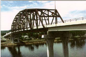
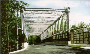
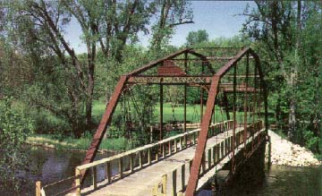
This historic wrought iron camel back truss is one of
the few remaining in the country. It has been preserved by moving it to a
new location, where it now serves as a footbridge.
(Baraboo, WI) |
Chapter 7BRIDGES AND OTHER MAJOR STRUCTURESRefer to Chapter V, VI, VII and X of the AASHTO Green Book |
 |
|
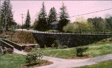
BACKGROUND Bridges and other related major structures play an important role in defining the manner in which a highway affects the aesthetic, scenic, historic, and cultural resources of the corridor within which it is located. Indeed, some of the distinguishing features of a number of major cities are their bridges. When one thinks of San Francisco, one of the first images that comes to mind is the Golden Gate Bridge. Smaller structures have a visual impact as well, such as the Manchester Street Bridge in Baraboo, WI, shown above.
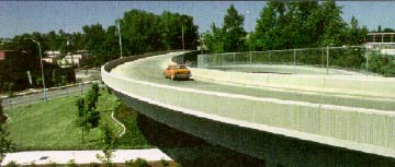
GENERAL GUIDELINES FOR THE GEOMETRICS OF BRIDGE DESIGN The geometric criteria in the AASHTO Green Book for new or replacement bridges deal primarily with the width of the bridge deck and its relationship to approach roads. Early design coordination is important when establishing the width of a new or replacement bridge and in determining its horizontal and vertical alinement. Road engineers, architects, and landscape architects, as well as members of the community, can provide input to help the bridge designer determine the appropriate geometric dimensions and overall appearance of the bridge. The AASHTO Green Book presents a range of options for traveledway widths for bridges with a span of less than 30 m, depending on functional classification and average daily traffic, as illustrated in the following tables.
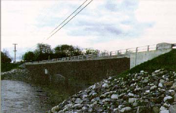
On urban collectors and arterials, the AASHTO Green Book recommends that the minimum clear width for new bridges be the same as the curbtocurb width of the approach street. In addition to determining the width of the travelway, a bridge designer must consider the need for pedestrian and nonvehicular traffic over the bridge and the most appropriate method for accommodating it. This could include a wide shoulder, a raised sidewalk, or both. If sidewalks are on the approach road, continuity of the sidewalk over the bridge is important. For existing bridges that do not meet the criteria for travelway width, the AASHTO Green Book recognizes that those that tolerably meet the criteria may be retained. It identifies some of the factors in considering the retention of existing bridges, including "the aesthetic value and the historical significance attached to famous structures, covered bridges, and stone arches" (p. 423). Because of this, AASHTO has criteria for minimum roadway widths and minimum structural capacities for bridges that are to remain in place. It is important to consider this option for each aesthetically and historically significant bridge on a casebycase basis, before deciding to demolish and replace it. BRIDGE DESIGN ELEMENTS In addition to determining the geometrics of a bridge, designers must consider many design elements. Basically, bridges are viewed from two perspectives. Traveling over the bridge deck, the driver of a vehicle sees the travelway, bridge railings, and the view to either side. If the bridge crosses over another roadway, water or land both on its side and underneath can also be viewed from this perspective. It is important for bridge designers to keep in mind that these two perspectives may require consideration of additional aesthetic treatments for the bridge. For the design of the bridge deck, the major components include the width of the travelway and shoulders and pedestrian and other nonvehicular accommodations, as mentioned above. Other components include railings, lighting fixtures, and other design details. For the side of the bridge, the major components include the piers, the side facia, abutments, and wing walls. In addition, the bridge railings and other fixtures selected for the top of the bridge will also play a design role for the side, because they can be seen from below.
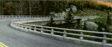
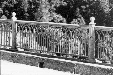
Bridge Railings When designing a bridge, designers can either choose to use a bridge railing that has already been designed and crash tested, or they can design a new one and have it crash tested. If designing a new railing, designers can use two AASHTO publications as guidance:
FHWA requires that the railings of all bridges on the NHS be crashtested and recommends following the crash testing procedures in National Cooperative Highway Research Program (NCHRP) Report 350, Recommended Procedures for the Safety Performance Evaluation of Highway Features, 1993. This report identifies six test levels for bridge railings which are intended to match the type of traffic and design speeds on the bridges. Currently, there are approximately 60 crashtested railing designs. These include steel bridge railings, solid concrete barriers, aluminum bridge railings, aesthetic steel pipe bridge railings, aesthetic stone masonryfaced concrete, and wood railings. Typically, each State has its own standard railings. The New Jersey and Fshape concrete safety shape bridge railings are the most commonly used for newconstruction projects. Because of the desire for aesthetic barriers, however, other types have been developed.
Bridges with lower traffic volumes, little truck traffic, and lower design speeds have the most options in terms of the types of bridge railings that have been crash tested. For instance, timber bridge railings have been developed for both longitudinal and transversely laminated wood bridge decks. In some cases, guardrailtobridge rail transition designs have been crash tested; in other cases, they have not. Often there is concern over designing bridge railings that prevent drivers from seeing through to the water or landscape below as they drive over the bridge. Solid concrete barriers may block the view, which many times is quite scenic. For this reason, bridge designers should consult the community when considering the type of railing to be used. There are metal railings that have been crash tested and approved by FHWA that allow the view to be maintained. State DOTS vary in their uses of these types of railings.
ISSUES The conflicts in design of highway bridges relating to aesthetic, scenic, historic, and cultural resources commonly boil down to one of two issues:
Reconstruction Versus Rehabilitation In many instances, particularly for bridges of historic or aesthetic value, the rehabilitation of the bridge is the preferred solution, rather than total replacement. This option is not always feasible, but should be pursued as much as possible. Solution As stated above, the AASHTO Green Book recognizes that existing bridges that tolerably meet geometric criteria can be retained. Each bridge needs to be examined on an individual basis, considering the design factors unique to that structure. Only after careful analysis and consultation with the community, should a determination be made.
This was the experience of the California Department of Transportation (Caltrans) with the rehabilitation of several steel truss structures along State Route 70 in Butte and Plumas Counties. The route has several unique features, including the bridges, all of which are of riveted steel construction in various truss and arch configurations. A 1985 project scoping report recommended demolishing the existing
structures and replacing them with more modern style steel or concrete
structures designed to satisfy current seismic design criteria. Caltrans
held a series of meetings with FHWA, the State Historic Preservation
Officer, and other State and local agencies in an attempt to develop
alternatives other than full bridge replacement. As a result of this finding, Caltrans staff developed several rehabilitation schemes designed to increase the structural capacity and seismic stability of the structures without changing their basic designs or appearances. These rehabilitation alternatives were presented at a public information meeting in April 1992 and met with great support. All the rehabilitation activities are being conducted in accordance with the Secretary of the Interior's Standards for Rehabilitation.
Another option that preserves structurally or functionally deficient bridges is to move them. This has been done successfully in many States. Often, the historic structure is moved to a location where it can serve as a bridge for a pedestrian or nonmotorized vehicle path. Compatible Design Scale When rehabilitation of existing bridges is not feasible, a common concern of local residents is whether the proposed new structure will visually "fit into" the community. Solution The solution for designing a visually attractive and contextsensitive new bridge is to be flexible and to work with the community from the beginning to obtain public input. Professionals from other disciplines, such as architects, can also assist, especially if engaged early in the design of the structure. It is important to consider how the use of the geometric criteria will affect the overall scale of the bridge and to consider how that scale will relate the bridge to its surroundings.
The New Hampshire Department of Transportation (NHDOT) proposed to demolish the historic twolane Oyster River Bridge, because of structural deficiencies and replace it with a fourlane structure on a higher elevation. When the original fourlane replacement concept was presented to the community, significant opposition arose, not only to the greatly enlarged scale of the proposed improvement, but also to the impact this option would have on adjacent 18th century houses, a community park, and a small cemetery. In a collaborative effort with the town of Durham and local residents, NHDOT staff undertook a reassessment of the project's scope to develop a design that was more compatible with its surroundings. The result of this effort was an awardwinning facility.
The newly reconstructed crossing provides two 3.6m (12ft) travel lanes and two 2.4m (8ft) shoulders and incorporates a lower vertical profile very close to that of its 1800's vintage predecessor. Much of the original stonework was used for facing of the abutments. While a number of bicyclists use the new bridge, a parallel bicycle/pedestrian crossing was constructed a short distance downstream to allow for better access to and from a riverside park. Although rehabilitation of historic bridges may be the preferred option, it is not always possible. The Oyster River Bridge is an excellent example of a new structure designed to be compatible with the scale of its surrounding environment. |
|
|
|