
4.0 Observations and Findings
This section presents the general test findings derived and determined from examination, interpretation, and analysis of all test data and information. It includes both general findings that relate to the standards as whole and specific findings that relate to a specific section or paragraph of each document.
The observations and findings are an amalgamation of those identified through static analysis of the standard, questionnaire interviews, and hands-on testing of the DMS controller. Additional findings were contributed from the following sources:
- Deployment and Testing of Updated DMS Standard – Virginia Tech, April 24, 2007
- ITS Standards Test Team – Testing conducted Summer 2007
- Trevilon 1203 Comments – Ken Vaughn, June 4, 2007
- VTTI Implementation Comments – LEDStar Inc.
- NTCIP v2.25 IBI Group Report – Virginia Tech Transportation Institute, March 30, 2007.
4.1 VTTI Findings
Acting in the role of the public agency, VTTI served to validate the processes put in place to specify, procure and test DMS' and management stations against the 1203 standard. As VTTI did not have specific comments against items in the standard (these were tracked by the vendors and integrator), VTTI did offer very valuable insight into their experience, and recommendations that should be considered in the standards development and deployment process as a whole. The following is excerpted from the VTTI Final Report data April 24, 2007.
4.1.1 General
The Version 2 specification methodology is a significant improvement over Version 1. VTTI's experiences demonstrate that the traceability aspect of the standard provided the ability to easily troubleshoot problems with the sign or software with pinpoint accuracy. However, more improvement in terms of user-friendliness and decision support is required to make deployment easier.
4.1.2 Specification Guide
The Specification Guide provided a step-by-step approach for developing the specification starting with the PRL table. While the process was straightforward and the PRL table focused on functional requirements, it was still difficult to complete for someone with limited DMS experience. Many of the issues that VTTI had with the PRL development centered on inexperience with basic DMS principles. Definitions of specifications such as message type, character sets, and events caused problems.
An electronics-based PRL with some built in error checking and decision support would help users to fill out the table faster and with less chance of human error.
4.1.3 Problems Experienced in Specification Development and Procurement
The completion of the PRL table is an exercise that lends itself to the development of an automated browser-based-form type of software. There are many instances where one entry in the PRL tables drives the answers for other entries. In many cases there are table entries that are duplicated several times. In any of these situations it is easy for an error to occur. An automated system can limit errors.
For example, if a MATRIX is chosen under entry 2.1.2.3.2, then any of the table entries that have a mandatory conformance for MATRIX can automatically be chosen by the system. This will reduce human error if someone mistakenly chooses incorrectly. At the same time, the form can 'gray out' or remove entries that are not applicable because they pertain to DRUM or other types of signs that are not MATRIX types.
Some entries such as D.3.1.2.1 Set_Time are repeated throughout the PRL table. If YES is chosen for this at the first occurrence, then the form can automatically enter YES for it at any other repeated entries. In other areas, you are only allowed to choose one option. An automated system can help the specification writer limit mistakes by not allowing them to choose more than one option in these situations.
There are many mandatory conformance entries that can automatically be filled out with YES, streamlining the process of filling out the table and decreasing any confusion as to whether or not a particular entry needs to be filled out. If NO is chosen for a major table heading, then all the entries under the heading can be 'grayed' out, preventing a user from mistakenly filling it out.
VTTI feels that the PRL methodology for creating a specification is definitely on the right track in terms of making the DMS standard user-friendly. The focus on User Needs and Requirements 'protects' the end user from the detailed bit level foundations of the standard. Yet the systems engineering approach of the Requirements Traceability Matrix (RTM) provides the ability for the vendors to build the products with only the PRL in hand.
4.1.4 Testing
4.1.4.1 Test Workshop
On March 2, 2006 a testing workshop for 1203 Version 2 was held at the VTTI facilities at the Smart Road. Representatives from VTTI, VDOT, Mitretek, and the ISTT attended. The workshop included a general introduction to the NTCIP testing process, tools, and test plan development. There was also significant hands-on using actual testing tools and test procedures. This report documents VTTI's comments about the testing phase after attending this workshop.
4.1.4.1.1 Knowledge Gained at the Testing Workshop
Prior to the testing workshop, VTTI was not very confident with regards to NTCIP testing procedures. On a scale of 1-5, VTTI's knowledge base in NTCIP was probably a 0.5-1. In fact, this limited knowledge was a desired component for testing the validity of the new Version 2 specifications process. However, during the testing workshop, the attendees often referred to Table 4.1 below taken from the INTERIM Student Workbook for the NTCIP 1203 Version 2 Testing Workshop:
| Task | NTCIP Knowledge Level (Low=1 to High=5) |
|---|---|
| Finalize Test Plan | 2 |
| Complete Test Transmittal Form | 1 |
| Perform Tests and Produce Test Log and Incident Reports | 5 |
| … | … |
VTTI's concern since approaching the testing phase has been the amount of NTCIP knowledge required in order to perform the tests. VTTI can safely say that after this testing workshop, NTCIP knowledge level had increased; however, it was still quite shy of Level 5.
Prior to the testing workshop, VTTI didn't have a grasp of how the different documents such as the PRL table of the RFP, the testing procedures, and the actual Standard cross-referenced each other. In fact, VTTI was somewhat unsure where to even start the testing procedures. Trevilon's presentation has answered most of VTTI's concerns regarding these issues. However, several more concerns were created.
4.1.4.1.2 New Issues Raised
In the testing workshop VTTI went through a typical testing example using the freely available EXERCISER tool. The example worked through included:
- Define variable values to be used for
- Define a Message
- Activate a Message
- Perform the following test
- Define a Message (2.3.7.2)
- Activate a Message (2.3.7.6)
EXERCISER provided the medium with which to send information to the sign; however, one also had to rely on an in-line protocol analyzer to determine if the results were correct. Analyzing the output of the protocol analyzer in order to determine a successful test required a fair amount of time.
Performing the above test – which is only one of more than 250 similar tests in the Test Procedures for the Virginia Early Deployment NTCIP DMSV2 (Version 1.03) – took more than one hour. After agonizingly working through this example, it was clear to VTTI that it is not realistic to perform the required testing using Exerciser. The program is old, buggy, and difficult to use. There are too many opportunities for user error. The sheer volume of the tests in the Test Procedures, combined with the slow interfacing between Exerciser and the sign controller, makes this method of testing totally unrealistic for VTTI.
The group then used NTester to work through a similar example. NTester is a much nicer interface than Exerciser and automatically checks the eight steps of verification of a command as defined in NTCIP 8007. However, even with NTester, VTTI was still required to manually step through a long procedure for something as simple as Define a Message (Test Case 7.2) which includes 48 distinct steps.
Even though NTester saved some time by automatically verifying if each step was performed correctly, it still took an incredible amount of time to manually work through each step.
It was VTTI's understanding that the NTester and similar tools have the capability for programming in macros to automatically step through the test procedures. However, currently there are only automated procedures for NTCIP DMS Version 1 and there are no automated procedures for Version 2 available. It is conceivable that VTTI could program the macros using NTester or other similar tools; however, the programming would take just as long as manually stepping through the test procedures with Exerciser. VTTI's lack of experience with the standard and the macro development process would also increase the risk of user error and increase the time required for macro development.
The workshop then discussed testing of Central Systems Software. VTTI had previously thought that the DMS testing was difficult. After discussing the process for verifying Central Systems Software, the DMS testing looked easy. In order to test the software isolated from the sign controller, one has to use FTS or a similar in-line protocol analyzer to look at the bit level output from the software. This is even more time consuming than the DMS testing and requires very high level knowledge of the standard.
There does not seem to be a realistic method for testing the software stand-alone. Testing the device first, then connecting the software to the device for a functional test seems more realistic.
The testing workshop was successful in providing the participants with the knowledge to move forward with developing a test plan. However, VTTI had significant concern on how to proceed with the actual implementation of the test plan given the current tools available at the time. It was unrealistic that the test procedures could be completed to success given the tools currently available at the time of the workshop. Some level of automated test procedures was required for DMS Version 2.
A decision was made to move forward with scripting the test procedures for Version 2.25 into Ntester.
4.1.4.2 Test Plan Development
Using a template in the Testing Workshop workbook, VTTI drafted a test plan. The biggest hurdle of the test plan was filling out a table of variables that would be used in the testing procedures.
The process of filling out the variable table was tedious and difficult. It required several steps of cross referencing between the variable table, the test procedures, the PRL table, and the 1203 Standard. In a few cases, the1201 Standard had to be referenced.
In addition to the difficulty caused from the cross referencing, there is significant level of detailed NTCIP knowledge required to complete the table properly. In several instances the user must fill out variables down to the bit level
For example:
Variable: Required Sign Technology
The sign is a light-emitting diode (LED) sign. The enumerated value for an LED sign as indicated by the NTCIP standard is 1. However, the correct answer for the variable table is:
This should be 'Bit 1' and the low order bit is 'Bit 0'; thus the value is 0000 0010 in binary or 2 in decimal.
Another example Required MULTI_Tag for the test case of Determine Message Display Capabilities:
The correct answer as indicated by Trevilon is:
Per the Ledstar PRL and NTCIP Clause 5.5.25; this should have the following bits set:
11, 7, 10, 6, 3, 9, 13, 12, 2, 14, 15, 21, 16, 17, 18, 19, 20, 21, 22, 23, 24, 25 (and bit 26 if the missing month bit is added); the bit string is:
2, 3, 6, 7, 9, 10, 11, 12, 13, 14, 15, 16, 17, 18, 19, 20, 21, 22, 23, 24, 25
0000 0011 1111 1111 1111 1110 1100 1100 = 0x03 FF FE CC = 67108556
In addition, there were several instances where VTTI entered a test message that was physically too long to be supported by the sign.
Based on these examples, there is an incredibly detailed high level of knowledge required to properly fill out the variable table. The main issue that has come up time and time again during this project has been the level of knowledge required to perform each stage from procurement through testing. The level of NTCIP understanding required to follow the specification guide and create a procurement document is significantly lower than what is required to complete testing. In this case, there is again a disconnect between the knowledge required to complete the PRL and to complete the variable table.
One of the outcomes of the specification guide development was that it shielded the user from the bit-level of the NTCIP standard. Rather, it allowed the user to develop a procurement based on concept of operations, and the bit-level detail was transparent to the specification writer.
It is VTTI's suggestion that the same philosophy needs to be applied to the Variable Table. VTTI has shown that an agency can complete the PRL table and develop a specification with limited NTCIP knowledge. Some level of decision support would be helpful to take the information from the PRL table and use it to automatically generate portions of the Variable table. Some user-defined information will be required (such as test messages), but for the most part the user should be separated from the bit-level of the standard as shown in the above examples.
VTTI's first attempt at filling out the variable table produced a large number of errors that initially rendered the table unusable. It is likely that a DOT that did go through the exercise would run into a similar experience which would significantly delay testing.
Considering how important the Variable Table is for the testing procedures, every effort should be made that it is completed correctly. In conclusion, VTTI feels that it would be prudent to take the effort to apply some level of decision support to the Variable Table in order to allow users with limited NTCIP knowledge the ability to realistically complete it properly.
4.1.4.3 Unit Testing of DMS
The final stage in this project involves the actual testing of the DMS and the Central Systems Software. Each component was procured completely independently of each other with only the PRL table provided to the vendor. A major goal of this entire project is to test if the standard and the PRL procurement method will support interoperability between multiple components.
This stage of the testing was difficult because, even though just sign/sign controller was the focus of attention, there were actually several components being tested.
- Test environment (cables/communications setting).
- Sign interface
- Procurement PRL
- Written Test procedures / test variables
- NTester testing tool procedures
- The standard itself
Each component listed above could be responsible for errors or failures incurred during the testing. In-depth analysis of using a line analyzer was required to determine where the responsibility for failures occurred. The traceability contained in the standard and the Systems Engineering Process made this possible. Without the RTM and the correlation between the User Needs→ PRL→ Requirements→ Test Cases it would be virtually impossible to determine what the underlying cause of a test case failure is.
Unit testing of the sign interface first ensures a known environment with which to test the central systems software integrated with the sign. The overall testing philosophy adopted by the testing team is that the central systems software integration could not proceed until the sign interface had tested to a minimum of 95% success.
The sign was tested first in an isolated environment. A special testing tool was used to exercise the testing procedures. NTester has been used successfully in the past with NTCIP Version 1. However, there were no automated scripts for the DMS II standard. This would have required a laborious manual testing procedure that would have taken several months.
It was decided that automated scripts should be developed specifically for DMS II in order to complete this testing. The automated scripts provided the macros necessary for running individual test cases. The definitions of the test scripts in XML are located in Appendix F of the VTTI Final Report. However, even with the test scripts, the testing was still very time intensive with much potential for human error.
4.1.4.4 DMS Testing Process
There were several steps that needed to be completed before actual testing could proceed. The specific test cases desired need to be selected and the variables used to exercise those tests have to be entered.
The first step in testing is to decide which test cases need to be run. The PRL table is the starting point for determining which test cases will be performed.
A User Need selected in the PRL table is traced to a requirement in the RTM which can then traced to a specific test case. The NTester software exercises the test cases. While the actual task of selecting a test is as simple as selecting it with a mouse, the process of manually transferring the selected User Needs in the PRL to the NTester software was laborious.
In the first version of NTester there was little correlation in the ordering of the User Needs/test cases in NTester and the PRL table. Initially, NTester did not have any ID numbers associated with the test cases. NTester was revised to add ID numbers and to alphabetize the test cases. These two refinements made the process of selecting test cases significantly easier.
This manual correlation between the PRL and the NTester software highlighted several problems with the original PRL table. Ideally, these problems should have been identified earlier during the initial PRL development. However, the fact that errors in the PRL table were uncovered through this testing process highlights the value of the traceability aspect of these procedures. For example, Table 4.2 below is taken directly from the Supplemental PRL table used in the RFP process. Requirement 3.5.6.2.5.1 (Support a Single Color Combination Per Message) was defined as NOT supported.
| Req ID | Requirement | Req ID | Requirement | Conformance | Support | Additional Specifications |
|---|---|---|---|---|---|---|
| 3.5.6.2.5.1 | Support a Single Color Combination per Message | O.6 (1) |  |
There are several other requirements that fall underneath this one such as 3.5.6.2.5.3 (Support a Color Combination for each Character). If the first has been set to NO, then the second should be NO by default. However, the PRL table had 2.5.6.2.5.3 specified as YES.
Several errors in the PRL that were related to user entry were uncovered during this process. In some cases as above, dependent requirements were chosen incorrectly. In other cases a requirement was not selected in the PRL but was referenced in the test plan template. These types of errors could be avoided with a more automated electronic entry of the PRL.
The second phase in setting up NTester to perform test cases was to enter in any variables that are required for a test case. The test plan developed using the template in the testing workshop book contains a table of variable values. Many of these variable values were pulled directly from the PRL table. Other variables were chosen ad-hoc strictly for the purpose of using them in test cases. Several problems were encountered related to variables.
The first problem was that several variables required for NTester had not been listed in the table used in the test workshop test plan template. For example, the variable Page_Text was required for NTester but was not listed in the template table.
Another problem encountered with variable entry is the high potential for user error. In some instances, VTTI entered a text value when a numerical value was required, such as with the variable ONCHANGE. Several other errors, such as forgetting a bracket on a tag or entering a decimal value when a hexadecimal value was expected, caused considerable problems when running tests.
An additional problem with variable entry stemmed from entering unrealistic variable values for the testing procedures. For example, the variable Delay_Time was set to 250 minutes. Similarly, a test message entered as a variable ended up being too long for this particular sign. This variable caused an error in the test and required a significant amount of time to troubleshoot that the failure was caused by an improper variable and not by the sign controller or the NTester software.While the Delay_Time entered value is perfectly valid, it is unrealistic to run the test procedures with a 250 minute delay between each step. These errors stem from VTTI's inexperience with the test procedures and, in several cases, variables were chosen completely arbitrarily without understanding of their consequences on the testing process.
4.1.4.5 Diagnostic Testing
A part of the testing that caused significant problems was the diagnostic portion of the testing. These test cases included exercising the photo sensor (Figure 7), the internal temperature sensors (Figure 8), LED boards (Figure 9), door sensors, power systems, and local/remote controls.
Variable value issues were again an issue with the diagnostic testing. For example, the event set for monitoring event changes was the temperature sensor warning. However, the team realized that a 10x change in the temperature was required to trigger this warning. The team was physically unable to create this type of delta. A better event to trigger the event monitoring was to change the message. Ledstar direct-connected to the sign and changed the message five times to create an event for this test case.
Again the values of the variables caused problems. For example, the variable for door access required a hexadecimal value. Initially VTTI's variable table had FRONT ACCESS and the enumerated value of 8. This value is actually wrong. The sign is Rear Access which has Bit2=1. In addition, a timeout value used in the variable table seemed to be causing failures even though the sign performed correctly. Initially the testing used a timeout of 200 ms and some diagnostic tests were failing. Changing to a 400 ms timeout resulted in a passing test. NTester needs to specify the units for this variable. It is also suggested that units be changed to milliseconds (ms). The actual value entered in NTester was 4.
One last suggestion is to build into the test tool or the testing plan a tracking methodology for documenting which requirements have been tested. One thing the team noticed is that several requirements are repeated throughout the test cases. To save time the team began skipping requirements that had previously passed in earlier test cases.
4.1.4.6 Summary of DMS Unit Testing Results
The detailed analysis of each test case performed can be found in the files DMS v2 sign unit testing results.XLS and Unit_testing_summary_v2 located in Appendix D of the VDOT/VTTI Final report.
The first round of testing yielded a fair amount of test case failures. However, the traceability of the test cases combined with documented FTS outputs and NTester outputs made diagnosing the reasons for the failures very easy. The total tally for Round 1 of the Ledstar unit testing is shown in Table 4.3.
| Round | Description Of Activity | Week of | Total # of Requirements Tested | % Passed | % Failed | % Indeterminate |
|---|---|---|---|---|---|---|
| 1 | Ledstar Unit Test | 1.14.07 | 170 | 27.3 | 62.5 | 10.2 |
Both Ledstar and Trevilon had issues that needed resolving in the sign controller and NTester. New versions of both were used in a second round of unit testing of the sign. This second round of testing proceeded significantly smoother given our better understanding of the test procedures and knowledge of where pitfalls lie. The results of the second round of testing are shown in Table 4.4.
| Round | Description Of Activity | Week of | Total # of Requirements Tested | % Passed | % Failed | % Indeterminate |
|---|---|---|---|---|---|---|
| 2 | Ledstar Unit Test | 2.05.07 | 174 | 95.4 | 2.9 | 1.7 |
One of the failures included a test case based on a requirement listed in the PRL that Ledstar did not implement, hence it was automatically failed.
4.1.4.7 Central Systems Software Testing
With the unit testing of the sign completed and verified to 95%+, the testing team moved forward with testing of the integrated system. This system consisted of the IBI Central Systems software connected to the Ledstar DMS. It is VTTI's understanding that typical testing of central software consists of functional tests to verify that the software is capable of communicating with the sign and can exercise the required functionality of the sign. No procedure was in place that correlated the central systems software with the User needs and associated requirements.
The software and the sign were procured using the PRL. This PRL and its associated user needs and requirements were used to develop extensive testing protocols with which the testing team was able to test and verify the operations of the sign. The priority goal of the central systems software testing was to develop a procedure which provides the capability to correlate the usage of the central software with specific User Needs and User Requirements.
4.1.4.8 Developing the Software Testing Procedures
There is so much ambiguity regarding how to test a management system that it was difficult to determine the best course of action for proceeding with the management station testing. It took two days to determine a viable procedure that was realistic to perform. The Ledstar testing produced a significant amount of useful data that highlighted the importance of correlating the user needs/requirements to specific test cases. The team felt it extremely important that the software testing followed a similar methodology so that the testing team could ‘compare apples-to-apples’.
The first option that the testing team pursued in order to use the traceability aspect in the IBI testing was to follow the Test Procedures for the Virginia Early Deployment of NTCIP DMSv2. In this document, there are columns for Device testing as well as Management Station testing. However, it should be kept in mind that these procedures were developed specifically for device testing and were adapted to testing management stations simply by stepping through the procedures and removing steps that did not apply to management stations.
The plan was to go through the steps in each test case and fill in Pass/Fail under procedures required for the management station. The device testing of the Ledstar sign followed these test procedures, however NTester had these test cases built into it. The automated NTester scripts stepped through the multiple procedural steps automatically. Currently, however, there are no automated scripts for exercising central systems software. Therefore, each procedural step had to be executed by hand in the software and verified with FTS before proceeding to the next.
This procedure proved to be an almost insurmountable task. For example, the simple functional requirement of DEFINE A MESSAGE (test case 7.2) has 45 individual procedural steps to it. Of these 45 steps, the management station test requires 33 steps to be performed. In each step, the FTS logs had to be checked in order to verify the step. The test procedure for DEFINE A MESSAGE took more than 2 hours to complete.
The test procedure for the similar task of ACTIVATE A MESSAGE (test case 7.6) also has a large number of steps. Even though these test procedures take an incredibly long time to complete, a bigger issue was that other test cases would reference test cases 7.2 and 7.6 multiple times. It quickly became apparent that using this test methodology on a management station was unrealistic.
To complete the testing in this manner would take months with many opportunities to introduce user error. Additionally, individual keystrokes in the software oftentimes exercised multiple test cases which make using the device test procedures on the management station very inefficient. It is highly unlikely that any agency would ever test management software with this methodology.
The next option that was explored was mapping keystrokes on the software to the User Needs identified in the PRL document used in the RFP. Prior to the testing, IBI had drafted an initial mapping of the software's keystrokes to user needs. Table 4.5 is an example of this initial mapping.
| User Need ID | Functional Requirement ID | Object ID | Object Name | Standard Dial. | Tab | Button Sequence |
|---|---|---|---|---|---|---|
| 2.4.1.1 Determine the DMS Identity | ||||||
| 3.4.1.1.1 | 5.2.2 | dmsSignType | No | Static Sign Info | Retrieve Data/Refresh button | |
| 5.2.9 | dmsSignTechnology | No | Static Sign Info | Retrieve Data/Refresh button | ||
| D.3.1.1 | 2.2 | globalMaxModules | No | Internal Events | Retrieve Data/Refresh button | |
| 2.3.1 | moduleNumber | No | Internal Events | Retrieve Data/Refresh button | ||
| 2.3.2 | moduleDeviceNode | No | Internal Events | Retrieve Data/Refresh button | ||
| 2.3.3 | moduleMake | No | Internal Events | Retrieve Data/Refresh button | ||
| 2.3.4 | moduleModel | No | Internal Events | Retrieve Data/Refresh button | ||
| 2.3.5 | moduleVersion | No | Internal Events | Retrieve Data/Refresh button | ||
| 2.3.6 | moduleType | No | Internal Events | Retrieve Data/Refresh button | ||
| D.3.1.4 | 2.4 | controller-baseStandards | No | Static Sign Info | Retrieve Data/Refresh button | |
In this mapping the functional requirements are mapped underneath the User Needs. Objects and their IDs that are required to perform the functional requirement are listed as well as the corresponding tab on the software and keystroke sequence. This mapping is the first step in correlating software keystrokes back to user needs. In addition, this type of mapping provides a frame of reference that is based on the standard to compare the software with the device testing.
As soon as the testing team began following the IBI mapping document, it became apparent that more work would be required to develop a proper testing procedure. The IBI mapping did correctly show the required keystrokes needed to exercise a particular user need. However, it failed to build in the logical sequence of steps that is truly required to perform certain steps.
For example, Table 4.6 (User Need 2.4.2.1 – Control a DMS from More than One Location) was mapped to the Internal Events tab on the Software and the Retrieve Data/Refresh button.
| User Need ID | Functional Requirement ID | Object ID | Object Name | Standard Dial. | Tab | Button Sequence |
|---|---|---|---|---|---|---|
| 2.4.2.1 Control a DMS from More than One Location | ||||||
| 3.4.2.1 | 5.7.1 | dmsControlMode | No | Internal Events | Retrieve Data/Refresh button | |
In order to properly test this user need requirement, a logical procedure is required that places the sign in the proper configuration. In this particular example, in order to verify valid performance of the user need of controlling the DMS from more than one location, several additional steps are necessary:
- Control from Central when in Central mode
- Get Control Mode
- Switch to Local Control
- Get Control Mode
- Attempt control from Central when in Local
- Override Local Control
- Get Control Mode
- Control when in Central Override
- Return to Central Control
The testing team used the IBI mapping as a starting point for developing a logical step-by-step procedure for testing the User Need.
The FTS line analyzer collected the communications between the Central Software and the sign as each procedure was performed. A testing log was created that correlated the FTS frames with the testing procedure. In real-time, the FTS logs were checked to verify if a step passed, failed or was indeterminate.
Table 4.7 is the actual testing log for User Need 2.4.2.1.
| Steps | Requirement | Tab | Process | Std | Frames | Results | Pass/Fail | |
|---|---|---|---|---|---|---|---|---|
| 1 | Control from Central when in Central Mode | 3.4.2.3.10.3 3.4.2.3.10.5 3.5.4.1 |
Sign Control | Type = 3 Number = 1 Get Message Change RunTimePriority = 2 Change MultiString Set Message |
 |
1-22 | PASS | |
| 1 | Get Control Mode | 3.4.3.1.5 | ||||||
| 2 | Flip to local control | <manual> | ||||||
| 2 | Get Control Mode | 3.4.3.1.5 | ||||||
| 3 | Attempt Control from Central when in Local | 3.4.2.3.10.3 3.4.2.3.10.5 3.5.4.4 |
Sign Control | Type = 3 Number = 2 Get Message Change RunTimePriority Change MultiString Set Message |
|
23-34 | PASS | |
| 4 | Override Local Control | 3.4.2.1 | Internal Events | Central Mode = CentralOverride | × | 35-36 | Noticed that IBI s/w includes local and central in the drop | PASS |
| 4 | Get Control Mode | 3.4.3.1.5 | ||||||
| 5 | Control when in Central Override | 3.4.2.3.10.3 3.4.2.3.10.5 3.5.4.3 |
Sign Control | Type = 3 |
|
37-66 | Local(2) Central(4) centralOverride(5) |
PASS |
| 6 | Return to Central Control | <manual> |
This type of testing procedure proved to be significantly more feasible than trying to adapt the Test Procedures used for the sign. The FTS logs combined with the Adobe Captivate screen captures provide adequate documentation such that any step in the procedure can be investigated in more detail. More importantly, the User Needs are the same user needs that can be traced back to test cases performed with NTester and the DMS sign.
There are some initial issues with the IBI software that became apparent upon moving forward with this procedure. IBI's interpretation of how to develop the software led to two totally separate interfaces: standardized and non-standardized. The standardized interfaces utilized what IBI felt were the standard dialogues as defined by in the NTCIP standards. IBI created the non-standardized interface to represent more typical user functionality. The majority of functions that needed to be exercised used non-standardized dialogues.
This issue was corrected by IBI and should be only one interface and all dialogues should be based on the standard. Oftentimes during our initial testing, the user had to switch multiple times between the standardized interface and the non-standardized interface. These steps are documented in the Adobe Captivate outputs.
While the procedures followed were in line with the Test Procedures developed for the sign, they were oftentimes not intuitive from a user's perspective. Take the User Need 2.4.2.3.1 – Activate and Display a Message (Table 4.8) for example. From a user's perspective, a successful test would involve activating and displaying a message. VTTI would consider the test passed once the message comes on screen. However, the standard also applies several supplemental requirements underneath this user need.
Therefore, the actual test procedure followed for 2.4.2.3.1 involved many more additional steps than one might expect. Agencies need to understand that testing in this manner may go well beyond what is expected from a functional perspective.
| Steps | Requirement | Tab | Process | Std | Frames | Results | Pass/Fail | |
|---|---|---|---|---|---|---|---|---|
| 1 | Retrieve a Message | 3.4.2.3.10.5 3.5.6.4 3.5.6.1 |
Sign Control | Type = 3 Number = 2 Get Message |
|
1-8 | PASS | |
| 2 | Activate a Message | 3.4.2.3.1 3.5.5.1.1 3.5.5.1.3 3.5.6.4 |
Sign Control | Change to non-std Activate |
x | 9-102 (non-std) 103-110 |
PASS | |
| 3 | Get Font CRC | 3.4.1.3.7 | Fonts | <non-std> --- Font Index = 2 <auto> Validate font (accessed sign via IBI's development system) |
x x |
111-144 145-146 147-272 273-306 |
fontVersionID = 55407 = 0xD86F | FAIL |
| 4 | Define a Font CRC Message | 3.4.2.3.10.3 | Sign Control | Message Type = changeable Message Number = 1 MultiString = [fo2,XXXX]VTTI[nl]TEST <where XXXX is the hex representation of the CRC retrieved in step 3> 'Set Message' button |
|
145-388 | Sign did not accept a mixture of upper and lower case in the font tag. | PASS |
| 4 | Change Font | 3.4.1.3.5 | Fonts | Change Line Spacing | x | 389-462 | Dialog should include a check of fontStatus to ensure that it changed to readyForUse | PASS |
| 5 | Activate Font CRC Message | 3.4.2.3.1 3.5.5.1.1 3.5.5.1.2 |
Sign Control | Activate | x | 463-500(auto) 501-512 |
Did not retrieve dmsActivateErrorMsgCode.0 until the very end of the process, which could result in race conditions | FAIL |
| 6 | Verify that the message did not display and that the response was correct | <manual> | PASS | |||||
| 7 | Activate a Message with 2-minute duration | 3.5.5.2 | Sign Control | Get Message 3.2 Select a Message Set Duration to 2 minutes Activate |
|
513-528 | No way to set the message duration within the user interface | Indeterminate |
| 8 | Delay 2 minutes | <manual> | ||||||
| 9 | Verify that sign blanks | <manual> | ||||||
| 10 | Activate a Message | 3.4.2.3.1 3.5.5.3 |
Sign Control | Change to non-std | x | 529-556 | PASS | |
| 11 | Retrieve Requester ID | 3.5.5.3 3.4.3.2.1 |
Sign Control | Current Message button | x | 557-582 | Many of the items were retrieved out of order and not grouped properly | FAIL |
| 12 | Retrieve a Message | 3.4.2.3.10.5 | Sign Control | Type = 3 Number = 1 Get Message |
x | 583-672 | ||
| 13 | Activate with an insufficient priority | 3.5.5.4 | No way to set the message activation priority within the user interface | FAIL | ||||
| 14 | Get the highest permanent message supported by the sign | 3.4.2.3.10.5 3.5.7.1 |
Sign Control | Type = 2 (permanent) Number = 1 Get Message |
x | 673-718 | Missing a request for PixelService | FAIL |
| 15 | Activate the Message | 3.4.2.3.1 3.5.7.1 |
Sign Control | Activate | x | 719-724 | PASS | |
| 16 | Get the highest changeable message supported by the sign per the PRL | 3.4.2.3.10.5 | Sign Control | Type = 3 (changeable) Number = 32 Get Message |
x | 725-1228 | Missing a request for PixelService for each message | FAIL |
| 17 | Download a Message | 3.4.2.3.10.3 | Sign Control | Message Type = changeable Message Number = 32 MultiString = Message 32 'Set Message' button |
x | 1229-1258 | Non-standard | |
| 18 | Activate the Message | 3.4.2.3.1 3.5.7.2 |
Sign Control | Activate | x | 1259-1264 | PASS | |
| 19 | Get the highest changeable message supported by the sign per the PRL | 3.4.2.3.10.5 3.5.7.3 |
Sign Control | Type = 4 (volatile) Number = 64 Get Message |
x | 1265-2038 | Missing a request for PixelService for each message | FAIL |
| 20 | Download a Message | 3.4.2.3.10.3 | Sign Control | Message Type = volatile Message Number = 64 MultiString = Volatile 64 'Set Message' button |
x | 2039-2068 | Non-standard | |
| 21 | Activate the Message | 3.4.2.3.1 3.5.7.3 |
Sign Control | Activate | x | 2069-2074 | PASS |
4.1.4.9 Summary of Software Testing Results
A detailed analysis of each test case can be found in the file DMS v2 IBI Testing Results v3.XLS located in Appendix E of the VTTI Final Report.
It was a surprise to everyone present when the testing team completed an entire run through the User Needs using this new procedure by the third day of testing. The testing team identified test cases that had previously been run and, as with the sign testing, did not run them multiple times.
The software generated several failures in these test procedures. However, the IBI programmer was able to quickly identify the causes for the failures because of the traceability documentation available in this process. Overall, approximately 80% of tests passed. IBI took the initial results and revising the software to address the issues identified. The results of round 3 of the testing are shown in Table 4.9.
| Round | Description Of Activity | Week of | Total # of Requirements Tested | % Passed | % Failed | % Indeterminate |
|---|---|---|---|---|---|---|
| 3 | IBI Integration Test | 2.12.07 | 154* | 59.2 | 35.6 | 4.2 |
A second round of testing on the software was performed during the week of March 12, 2007. Initially, any errors found were straightforward and easy to debug using the testing methodology the testing team had developed. The results of the final round of testing of the integrated system are shown in Table 4-10.
| Round | Description Of Activity | Week of | Total # of Requirements Tested | % Passed | % Failed | % Indeterminate |
|---|---|---|---|---|---|---|
| 4 | IBI Integration Test | 3.12.07 | 155 | 100 | 0 | 0 |
4.1.4.10 Suggestions for Improving the Testing Process
The final results of the testing were quite amazing considering that the vendors developed their products using only the PRL table and with NO interaction. However, the testing procedure itself was very difficult. There are several key areas where the testing area can be improved to make testing like this more realistic from an agency point of view.
In VTTI's opinion, the biggest area of improvement lies in providing more decision support to the end user. This support should start with a computer controlled PRL entry system. There are several benefits to an electronically entered PRL table, such as providing some level of error checking and porting the PRL into the Variable Table and the testing tool. Figure 4.1 shows that the PRL is the driving force behind the Variable Table and the testing exerciser. Much of the information in the PRL can be ported directly into the testing process.
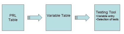
Figure 4.1. Schematic of PRL Information Flow
A manually-entered PRL provides too many opportunities for user error. Trevilon's analysis of VTTI's variable table indicated that 36% of the errors were due to strings that were too long for the sign to project and 28% were due to entering the wrong value in the variable value table. These errors in the initial PRL could be avoided all together with some built-in error checking. For example, if a main requirement heading is set to NO, then every dependent requirement should be grayed out so that the user cannot select them. In addition, some level of error checking can be applied to warn the user if variables lie outside ‘realistic’ values.
The PRL entry needs to be more user-friendly. For example, for sign access a pull down menu would allow choices for Front, Rear, or both. An end user need only choose the desired option. In the current PRL, a user must find the door access definition in the standard and then enter the enumerated value listed in the standard. In some cases the hexadecimal value of the decimal enumeration is required. These types of entries need to be avoided all together and the end user needs to be separated from this enumeration of items such as sign access.
Similarly, multi-tag message variables provide opportunity for user error. For example, the below multi-string took several tries to get right.
[flt10o10][jl2]VTTI[f9,2][f8,2][/fl][nl][flt10o10][jl2]VTTI[f9,2][f8,2][/fl][nl][flt10o10][jl2]VTTI[f9,2][f8,2][/fl][np][flt10o10][jl2]VTTI[f9,2][f8,2][/fl][nl][flt10o10][jl2]VTTI[f9,2][f8,2][/fl][nl][flt10o10][jl2]VTTI[f9,2][f8,2][/fl][np][flt10o10][jl2]VTTI[f9,2][f8,2][/fl][nl][flt10o10][jl2]VTTI[f9,2][f8,2][/fl][nl][flt10o10][jl2]VTTI[f9,2][/fl]
An electronic PRL would also help minimize repeat entries. In some cases the same item was called for in the PRL; however, VTTI entered different values each time. An electronic PRL would automatically fill in the entry in every location of the PRL when entered the first time.
The information entered into the PRL could be ported directly into a testing tool to avoid the user having to re-enter information already available in the PRL. For example, the PRL directly drives which test cases are required to be run. Selecting the test cases takes considerable time. Any opportunity to avoid human error should be utilized. Initial variable settings could be pulled directly from the PRL.
The next major area where the testing can be improved is with regards to the use of variables in the testing tool. Variable entry is important to proper testing to ensure that a vendor does not 'hard code' known variables into the product. However, in many cases the variable entry caused significant problems. These problems included slowing down the testing process by virtue of hand entering values and causing test failures due to using unrealistic or incorrectly formatted variables.
Many of the variables are only used for the test cases and have no use in the actual operation of the sign. In these cases, the user can be asked for a random seed instead of an actual variable. The testing tool can use the random seed to create a variable strictly for the purpose of the test. This randomly generated variable would solve two problems. It would save considerable time for the user by minimizing the hand entering of variables. In addition, it would also minimize the entry of unrealistic variables as the testing tool would be able to set realistic ranges for the variables.
Another area that needs improvement is the actual test procedures used by the testing exerciser. The step-by-step test procedures must be verified better to avoid ambiguous situations. For example, NTester would ask the user to verify that the sign is blanked. However, oftentimes the sign was already blank after the end of the previous test. This creates an ambiguous situation because the user is not certain whether the sign blanked or if it was blank to begin with.
In other test cases, the fonts were manipulated and had to be restored manually prior to proceeding with the testing. It took some troubleshooting to determine that the fonts needed to be restored. The testing tool needs to tell the user when tasks like this are required in order for testing to proceed.
The diagnostic procedures especially need to be verified for correctness or the instructions need to be detailed better. For example, the testing of the temperature warning had to be repeated several times because the step-by-step procedure was ambiguous.
4.1.4.11 VTTI Conclusions on Testing
Considering that the sign and the software were developed completely independently of each other, the fact that they even communicated at all is impressive. The majority of failures encountered were caused by minor interpretation issues with the standard or programming bugs. The rigorous testing procedures provided the IBI and Ledstar programmers with the information necessary to implement fixes.
A great success of this endeavor has been the development of a systematic procedure for the testing of central systems software. To date, this has never been done. While the test procedure developed is somewhat customized to this particular piece of software, it can be used as a template for the development of a basic procedure for future deployments similar to the testing procedures developed for signs.
This procedure is significantly more rigorous than the typical functional testing that a user would perform. However, the advantage to performing a detailed standards-based testing on the software is huge. This type of testing allowed us to specifically identify where problems occurred down to the bit level. More importantly, the procedures allowed us to identify whether the problem was with the sign, the software, or caused by an ambiguity in the standard.
The ambiguities identified through the testing process have been listed in the file 1203 Comments.doc located in Appendix F of the VTTI Final Report and are also included in section 4.3 of this report.
The ability to pinpoint with a high degree of accuracy where the issues lie cannot be overemphasized to the end user. During our testing, the testing team identified problems in both the sign and software as well as identifying ambiguities in the standard. Throughout the process, it was highlighted how well each of the vendors was working with us. In all situations the vendor was able to view the FTS logs and readily acknowledged whether the problems were with the product or stemmed from ambiguity or misinterpretation of the standard. The vendors then developed a plan for how to address the situation.
The experience during this testing was contrasted to the typical experience seen by DOTs when integrating multiple pieces of a system. Oftentimes vendors are reluctant to accept responsibility for issues and blame other parties. By following test procedures that are built upon traceability between User Needs, User Requirements, and test cases, it was easy to isolate exactly where an issue was. More importantly, there was no argument from the vendor and no ‘blame game’.
While these procedures may take longer to perform, there is no doubt in VTTI's mind that this process provides the foundation for the DOT to assign responsibility for problems found. This ability will save a significant amount of money and time and lead to faster deployments.
4.1.4.12 VTTI Overall Conclusions
The experiences of specification, procurement, and testing were difficult and each one presented significant roadblocks to an agency with limited NTCIP knowledge, such as VTTI. However, the results of these activities produced many suggestions for improving the processes. Overall, VTTI feels that the project has been a resounding success.
The specification process meets the goals of creating a more user-friendly environment for an agency to develop procurements. However, VTTI feels there is room for improvement in terms of making the PRL electronically based and developing more user decision support to prevent errors. This decision support and electronic PRL can transition from specification directly into test plan development as well as testing.
There has been significant improvement to the specification process between Version 1 and Version 2. This same attention needs to be given to the testing aspect as well. The entire process from specification through testing needs to be developed in concert to ensure successful deployments.
The testing results, coupled with the fact that each component was developed in complete isolation of other components, speak volumes regarding the validity of the Version 2 foundation of traceability. The most significant aspect of the traceability to VTTI was the capability for troubleshooting problems. The testing team was able to quickly identify problems and assign responsibility. This process fostered an amicable environment between the agency and the vendor which produced very fast resolution to problems.
4.2 ISTT Findings
| Item | 4.2.1 |
| Document | NTCIP 1203 DMS v2.25 |
| Page | General |
| Paragraph | General |
| Title | Pixel Bit-Mapping is Inconsistent |
| Comment | The standard specifies that when defining image bitmaps for font characters or graphics that the Most Significant Bit (MSB) of the bitmap corresponds to the upper leftmost pixel of the display. However the [dmsPixelStatus] bitmap specifies that its Least Significant Bit (LSB) corresponds to the upper leftmost pixel. This is a point of confusion since the data contained in these objects are similar in nature but use an opposite convention. |
| Recommendation | For clarity, all pixel-related bitmap data objects should use a similar convention for encoding their pixel information |
| Item | 4.2.2 |
| Document | NTCIP 1203 DMS v2.25 |
| Page | General |
| Paragraph | General |
| Title | Mandatory Data Objects are Ambiguous |
| Comment | The standard provides a Protocol Requirements List (PRL) and a Requirements Traceability Matrix (RTM) that together provide mapping between the user needs, the functional requirements, and the data objects as illustrated in Table A and Table B. Table A. Excerpt from Protocol Requirements List Table B. Excerpt from Requirements Traceability Matrix The PRL specifies which functional requirements are mandatory for each user need; however the Traceability Matrix does not specify which data objects, if any, are mandatory to implement each functional requirement. This implies to a reader that all of the data objects associated with a mandatory functional requirement should themselves also be considered mandatory, which may not always be true. The confusion of this ambiguity only deepens when considering the actual data object definitions, which specify that each data object is optional as shown in the following ASN.1 notation excerpts. Paragraph 5.2.2 Paragraph 5.2.9 |
| Recommendation | It is counter-intuitive to specify that a functional requirement is mandatory but the data objects that embody it are all optional. As such, it would be instructive to specify which data objects must be implemented for each functional requirement. The Requirements Traceability Matrix should specify the conformance requirements of each data object and the status attribute of the ASN.1 notation for each data object should be updated to reflect its conformance requirement. |
| Item | 4.2.3 |
| Source | ISTT Findings |
| Document | NTCIP 1203 DMS v2.25 |
| Page | General |
| Paragraph | 3.4.3.2 |
| Title | Monitor the Current Message |
| Comment | The content of this paragraph is duplicated in paragraph 3.4.3.2.1. |
| Recommendation | Eliminate duplicate text. |
| Item | 4.2.4 |
| Source | ISTT Findings |
| Document | NTCIP 1203 DMS v2.25 |
| Page | General |
| Paragraph | 4.3.1.3 |
| Title | Delete a Font |
| Comment | The dialog to delete a font references the [dmsFontStatus] and the [dmsFontHeight] data elements, which are the wrong names for these data objects. The correct names for these data objects are [fontStatus] and [fontHeight]. |
| Recommendation | Correct the error in the standard. |
| Item | 4.2.5 |
| Source | ISTT Findings |
| Document | NTCIP 1203 DMS v2.25 |
| Page | General |
| Paragraph | 4.3.3.10 |
| Title | Monitor Sign Housing Humidity |
| Comment | The standard does not differentiate between the humidity sensors for the sign housing and control cabinet. |
| Recommendation | This paragraph should be deprecated since paragraph 4.3.3.11 specifies the proper dialog to monitor the humidity sensors. |
| Item | 4.2.6 |
| Source | ISTT Findings |
| Document | NTCIP 1203 DMS v2.25 |
| Page | General |
| Paragraph | 5.5.6 |
| Title | defaultFlashOnActivate |
| Comment | The standard specifies an incorrect node identifier for the [defaultFlashOnActivate] data object that does not match the name of the parent node. |
| Recommendation | The proper node identifier should specify this data object as element 17 in the [multiCfg] node as shown in the following ASN.1 notation excerpt.
defaultFlashOnActivate OBJECT-TYPE |
| Item | 4.2.7 |
| Source | ISTT Findings |
| Document | NTCIP 1203 DMS v2.25 |
| Page | General |
| Paragraph | General |
| Title | Invalid Octet String Size Syntax |
| Comment | Five data objects in the standard have ASN.1 notation that has invalid syntax to specify the size of the octet strings. The ASN.1 notation for these data object use (SIZE (1 | 3)) rather than (SIZE (1..3)). This comment applies to the following data objects: ¶5.5.19 Default Background Color RGB Parameter |
| Recommendation | Correct the objects as indicated. |
| Item | 4.2.8 |
| Source | ISTT Findings |
| Document | NTCIP 1203 DMS v2.25 |
| Page | General |
| Paragraph | 5.7.15 |
| Title | dmsEndDurationMessage |
| Comment | The ASN.1 syntax for the default value of the [dmsEndDurationMessage] is invalid. |
| Recommendation | Correct this error. |
| Item | 4.2.9 |
| Source | ISTT Findings |
| Document | NTCIP 1203 DMS v2.25 |
| Page | General |
| Paragraph | 5.11.2.2.3.5 |
| Title | dmsPowerType |
| Comment | The object definition for the [dmsPowerType] data element is missing its node tag from the ASN.1 notation. It should be element 5 of the [DmsPowerStatusEntry] node as shown in the following ASN.1 notation excerpt. dmsPowerType OBJECT-TYPE The [dmsPowerType] data element should also be included in the [DmsPowerStatusEntry] sequence as shown in the following ASN.1 notation. DmsPowerStatusEntry ::= SEQUENCE { |
| Recommendation | Implement changes as specified in above comment. |
| Item | 4.2.10 |
| Source | ISTT Findings |
| Document | NTCIP 1203 DMS v2.25 |
| Page | General |
| Paragraph | 5.11.2.3.5 |
| Title | DmsClimateCtrlStatusEntry |
| Comment | The elements defined in the [DmsClimateCtrlStatusEntry] sequence are different then the elements defined in sub-paragraphs 5.11.2.3.5.1 through 5.11.2.3.5.7 as illustrated in the following table: DmsClimateCtrlStatusEntry ::= SEQUENCE ¶ 5.11.2.3.5.1 dmsClimateCtrlIndex The definition for the climate control status table entry sequence is incorrect. |
| Recommendation | The standard should specify this sequence as shown in the following ASN.1 excerpt. DmsClimateCtrlStatusEntry ::= SEQUENCE |
| Item | 4.2.11 |
| Source | ISTT Findings |
| Document | NTCIP 1203 DMS v2.25 |
| Page | General |
| Paragraph | 5.11.2.4.2 |
| Title | pixelFailureTable |
| Comment | The standard specifies the [pixelFailureTableNumRows] data object to provide the number of rows that exist in the [pixelFailureTable] table. However, this data object has a deprecated status leaving no means to identify the number of table rows. The standard provides the following two data objects: [dmsPixelFailureTestRows] [dmsPixelFailureMessageRows] This data object indicates the number of rows in the [pixelFailureTable] with a failure detection type equal to [messageDisplay]. It is possible that the sum of these two data elements is intended to indicate the total number of table rows; however the standard is not clear on this point. |
| Recommendation | The standard should clarify the mechanism by which the number of table entries is specified. |
| Item | 4.2.12 |
| Source | ISTT Findings |
| Document | NTCIP 1203 DMS v2.25 |
| Page | General |
| Paragraph | 5.11.2.4.4 |
| Title | dmsPixelStatusTable |
| Comment | The standard specifies that the [pixelFailureTableNumRows] data object is to provide the number of rows that exists in the [dmsPixelStatusTable] table. However, this data object has a deprecated status leaving no means to identify the number of table rows. The number of entries in this table is the same as that of the [pixelFailureTable] table. |
| Recommendation | Correct the standard to eliminate use of deprecated object. |
| Item | 4.2.13 |
| Source | ISTT Findings |
| Document | NTCIP 1203 DMS v2.25 |
| Page | General |
| Paragraph | 5.11.2.4.4 |
| Title | PixelFailureStatusEntry |
| Comment | The elements defined in the [PixelFailureStatusEntry] sequence are different than the elements defined in sub-paragraphs 5.11.2.4.4.1 through 5.11.2.4.4.2 as illustrated in the following table: PixelFailureStatusEntry ::= SEQUENCE 5.11.2.4.4.1 dmsPixelStatusIndex The definition for the pixel failure status entry sequence is incorrect. The standard should specify this sequence as shown in the following ASN.1 excerpt. PixelFailureStatusEntry ::= SEQUENCE The standard specifies an incorrect node identifier for the [pixelFailureStatusEntry] data object that does not match the name of the parent table. The proper node identifier should specify this data object as the first element in the [dmsPixelStatusTable] node as shown in the following ASN.1 notation excerpt. pixelFailureStatusEntry OBJECT-TYPE |
| Recommendation | Implement changes as recommended above. |
| Item | 4.2.14 |
| Source | ISTT Findings |
| Document | NTCIP 1203 DMS v2.25 |
| Page | General |
| Paragraph | 5.11.2.5.5.1 |
| Title | dmsLampIndex |
| Comment | The [dmsLampIndex] data element is the index to the lamp status table and specifies that an index value of 1 corresponds to the low-order bit of the lamp status map. However, the data object definition for the [dmsLampStatusMap] data element is missing from the standard. |
| Recommendation | It should be specified as element 22 of the [StatError] node as shown in the following ASN.1 notation excerpt. dmsLampStatusMap OBJECT-TYPE |
| Item | 4.2.15 |
| Source | ISTT Findings |
| Document | NTCIP 1203 DMS v2.25 |
| Page | General |
| Paragraph | General |
| Title | dmsHumiditySensorNumRows |
| Comment | The object definition for the [dmsHumiditySensorNumRows] data element is missing from the standard |
| Recommendation | It should be element 32 of the [StatError] node as shown in the following ASN.1 notation excerpt. dmsHumiditySensorNumRows OBJECT-TYPE |
| Item | 4.2.16 |
| Source | ISTT Findings |
| Document | NTCIP 1203 DMS v2.25 |
| Page | General |
| Paragraph | 5.12.8 |
| Title | DmsGraphicEntry |
| Comment | The elements defined in the [DmsGraphicEntry] sequence are different than the elements defined in sub-paragraphs 5.12.8.1 through 5.12.8.10 as illustrated in the following table: DmsGraphicEntry ::= SEQUENCE ¶ 5.12.8.1 dmsGraphicIndex |
| Recommendation | The definition for DMS graphic sequence is incorrect. The standard should specify this sequence as shown in the following ASN.1 excerpt. DmsGraphicEntry ::= SEQUENCE |
| Item | 4.2.17 |
| Source | ISTT Findings |
| Document | NTCIP 1203 DMS v2.25 |
| Page | General |
| Paragraph | 5.11.2.8.2.1 |
| Title | dmsHumiditySensorIndex |
| Comment | The description field for the [dmsHumiditySensorIndex] data element refers to a non-existent [dmsHumiditySensorsSignHousingRows] data element for indexing control cabinet sensors. |
| Recommendation | This clause should be corrected and clarified with an example. |
| Item | 4.2.18 |
| Source | ISTT Findings |
| Document | NTCIP 1203 DMS v2.25 |
| Page | General |
| Paragraph | 6.4.9 |
| Title | Line Justification |
| Comment | For center justification, the standard does not specify if the rules for an extra space apply only to character matrix signs or to both character and full matrix signs. There is also no description on how full justification is to be accomplished; should character spacing be increased or should the spaces between words be increased. |
| Recommendation | Add text to support these findings. |
| Item | 4.2.19 |
| Source | ISTT Findings |
| Document | NTCIP 1203 DMS v2.25 |
| Page | General |
| Paragraph | General |
| Title | Comments on the Requirements Traceability Matrix |
| Comment | There are numerous functional requirements that have interfaces that include references to table objects defined in the standard. The tables are not data objects and do not need to be referenced directly by the interface. Rather, the interface definitions need only reference the data objects that make up the entries in the tables. |
| Recommendation | These erroneous references should be deleted. |
4.3 Trevilon Findings
| Item | 4.3.1 |
| Source | Trevilon Findings – 1203 Comments |
| Document | NTCIP 1203 DMS v2.25 |
| Clause | 173 |
| Paragraph | 5.2.1 |
| Comment | All Bitmapped values have ambiguity. Is there always a Bit 0? Is Bit 0 the low or high order bit? Does this vary for each object, object syntax, etc.? The ASN.1 standards define Bit 0 for INTEGERs to be the low order bit, whereas Bit 0 for a BIT STRING is defined as the first (high-order) bit. However, BIT STRING is not a supported SNMP type and the interpretation for an OCTET STRING is unclear. The original version of NTCIP 8004 was silent on this issue, but the most recent draft has added text suggesting that Bit 0 is always the low-order bit. Further, this interpretation of ASN.1 standards appears to conflict with some of the text in some of the objects within 1203. This issue affects the following objects (at a minimum) with an indication if the text for each: dmsSignAccess dmsSignTechnology fontSupported CharacterSet characterBitmap dmsSupportedMultiTags dmsStatDoorOpen shortErrorStatus controllerErrorStatus dmsPowerStatusMap fanFailures dmsClimateCtrlStatusMap pixelFailureStatus dmsPixelStatus lampFailureStuckOn lampFailureStuckOff dmsDrumStatusMap dmsLightSensor dmsHumiditySensor dmsTempSensor tempSensorWarningMap tempSensorCritical dmsGraphicBlockBitmap |
| Suggestion | Rather than repeating much of the definition for each object, the objects should use textual conventions with the definition of the textual convention used to explain its interpretation. For example, define INTEGER – Although the INT objects are generally silent on order, I think the NTCIP community is in agreement that the low-order bit of an INTEGER is Bit 0. However, this should be formally defined somewhere to remove ambiguity (e.g., in the definitions section or at the beginning of the MIB) and does not even require a textual convention, although one could be defined. this would apply to the following objects: dmsSignAccess shortErrorStatus should denote Bit 0 as being reserved to prevent confusion into thinking that there is not a Bit 0. Most of the OCTET STRINGS appear to have some text (in the object definition or a related object definition) that defines the convention of low-order bit being Bit 0 and corresponding to Row 1 in any associated table. I suggest that this convention be defined as a BITMAP and that this SYNTAX be applied to the following objects: dmsPowerStatusMap The following objects probably should follow the same convention, but the text would seem to suggest otherwise at present: tempSensorWarningMap tempSensorCriticalTempMap dmsSupportedMultiTags is completely silent on the ordering of bits; however, it also has other problems that need to be clarified, so the best approach may be to deprecate the object and define a new one. fanFailures is a deprecated object already and thus is best left as is (ambiguous, but essentially mfr-specified) The following objects use OCTET STRINGS to define the state of pixels starting with the upper left being the high-order bit and zero padding at the end of the string. This is consistent with the ASN.1 definition of a BIT STRING. I recommend defining a BITSTRING textual convention to support this definition and to assign this convention to these two objects. The text should also include a note pointing out that this is different from the BITMAP convention dmsGraphicBlockBitmap dmsPixelStatus seems counter intuitive since it uses the opposite convention as used in characterBitmap and dmsGraphicBlockBitmap in order to achieve the same basic concept. If this ordering is kept, the difference should be clearly pointed out so that there is no confusion. Alternatively, it may be appropriate to deprecate the object and create a new object that uses the same ordering as characterBitmap. |
| Item | 4.3.2 |
| Source | Trevilon Findings – 1203 Comments |
| Document | NTCIP 1203 DMS v2.25 |
| Page | 50 |
| Clause | PRL Item 3.4.3.2 |
| Comment | The standard should provide a PRL variable to define the maximum character size. |
| Suggestion | Add an additional specification for the character sizes that the DMS is required to support; also add default text in the body of the requirement. |
| Item | 4.3.3 |
| Source | Trevilon Findings – 1203 Comments |
| Document | NTCIP 1203 DMS v2.25 |
| Page | 52 |
| Clause | PRL Item 3.4.2.4 |
| Comment | The standard does not state how quickly the dmsMemoryMgmt object must clear messages; we probably need a catch all requirement for how quick operations must be performed unless there is an explicit exception taken. |
| Suggestion | Add an additional specification for the maximum amount of time that the DMS may take to clear the memory; also add default text in the body of the requirement. |
| Item | 4.3.4 |
| Source | Trevilon Findings – 1203 Comments |
| Document | NTCIP 1203 DMS v2.25 |
| Page | 56 |
| Clause | General |
| Comment | Item 3.4.3.3.4 (Power Loss Message) in the PRL should constrain the conformance of the requirement to FlipDisk signs. |
| Suggestion | Change the Conformance column to read: FlipDisk:M |
| Item | 4.3.5 |
| Source | Trevilon Findings – 1203 Comments |
| Document | NTCIP 1203 DMS v2.25 |
| Page | 67 |
| Clause | PRL Item D.3.2 |
| Comment | D.3.2 items in the PRL should be mandatory |
| Suggestion | Correct conformance |
| Item | 4.3.6 |
| Source | Trevilon Findings – 1203 Comments |
| Document | NTCIP 1203 DMS v2.25 |
| Page | 68 |
| Clause | PRL Item 3.5.13 |
| Comment | Should be 3.5.12 |
| Suggestion | Correct reference |
| Item | 4.3.7 |
| Source | Trevilon Findings – 1203 Comments |
| Document | NTCIP 1203 DMS v2.25 |
| Page | 68 |
| Clause | PRL Item 3.5.14 |
| Title | Correct Reference in PRL 3.5.14 |
| Comment | Should be 3.5.13 |
| Suggestion | Correct reference |
| Item | 4.3.8 |
| Source | Trevilon Findings – 1203 Comments |
| Document | NTCIP 1203 DMS v2.25 |
| Page | 89 |
| Clause | 3.5.5.4 |
| Comment | This clause is in conflict with Clause 5.1. The text should state "greater than or equal to" not "greater than". |
| Suggestion | Correct the text |
| Item | 4.3.9 |
| Source | Trevilon Findings – 1203 Comments |
| Document | NTCIP 1203 DMS v2.25 |
| Page | 90 282 |
| Clause | 3.5.6.2.5.3 6.4.1 2nd para |
| Comment | Clause 3.5.6.2.5.3 is in conflict with the MULTI definition that suggests that there should only be a single background color. Please correct. |
| Suggestion | Make the text consistent with one another |
| Item | 4.3.10 |
| Source | Trevilon Findings – 1203 Comments |
| Document | NTCIP 1203 DMS v2.25 |
| Page | 93 195 |
| Clause | 3.5.8.2 5.5.24 |
| Comment | The dmsColorScheme object should be clarified to explain that a single-color sign must be defined as a monochrome1bit and not colorClassic per the Requirement definition |
| Suggestion | Clarify object definition to explicitly state the requirement where someone may be looking for the restrictive text |
| Item | 4.3.11 |
| Source | Trevilon Findings – 1203 Comments |
| Document | NTCIP 1203 DMS v2.25 |
| Page | |
| Clause | New Req |
| Title | |
| Comment | The standard appears to be missing an explicit requirement to allow the shortening or lengthening of the duration of a message; I believe this was the intent behind making dmsMessageTimeRemaining a read-write object. |
| Suggestion | Add a requirement to change the remaining duration of a message. |
| Item | 4.3.12 |
| Source | Trevilon Findings – 1203 Comments |
| Document | NTCIP 1203 DMS v2.25 |
| Page | 95 |
| Clause | New Req |
| Comment | The text of all NTCIP Information Level standards should ensure that the requirements apply equally to management stations as to devices. Each group should exert some effort ensuring that all conditions are met (e.g., is the management station required to allow a system operator to set the duration and/or activation priority of a message?) Also see 2.4.2.3.2; it suggests that a user should be able to set priority -- is this to any value? Does this mean that a system that constrains the standard operator to lower priorities than the administrator is non-conformant? How many permanent, changeable, and volatile messages must a system support? Do we need to add text to assist users in considering this issue? |
| Suggestion | Add Requirement 3.6 as follows: 3.6.2 Conformant Management Station 3.6.3 Consistent Management Station As long as the dialog is designed so that any sign conforming to the subject requirement will successfully interoperate with the management station, the dialog is deemed to be consistent. This might mean that the management station requests other data in separate messages and is able to handle the 'noSuchName' errors without affecting the operation of the subject requirement, or the management station may request all of the data in a single request and upon the receipt of a 'noSuchName' error be designed to fallback and issue a series of smaller requests that will work to fulfill the requirement. |
| Item | 4.3.13 |
| Source | Trevilon Findings – 1203 Comments |
| Document | NTCIP 1203 DMS v2.25 |
| Page | 107 |
| Clause | 4.3.1.4 |
| Comment | The purpose of the CRC values (e.g., fontCRC, messageCRC, etc.) are to ensure consistency between the management station and the device and that the subject item was not somehow corrupted by other processes (e.g., 3.4.2.3.3.4). However, the standard does not currently require the management station to independently calculate these CRC values. The standard should be revised to require this in order to ensure that the design fulfills the requirement. |
| Suggestion | Add steps in the dialog that requires the management station to independently calculate the CRC so that it is not a simple comparison to a previously read value. |
| Item | 4.3.14 |
| Source | Trevilon Findings – 1203 Comments |
| Document | NTCIP 1203 DMS v2.25 |
| Page | 110 269 |
| Clause | 4.3.1.7 5.12.8.4 |
| Comment | The process to delete a graphic requires the management station to set dmsGraphicHeight to zero (0); however, this object has a range starting at one (1). |
| Suggestion | The object range should be changed so that the design can remain consistent with the Font Deletion process. |
| Item | 4.3.15 |
| Source | Trevilon Findings – 1203 Comments |
| Document | NTCIP 1203 DMS v2.25 |
| Page | 114 151 |
| Clause | 4.3.2.2 4.4.6.3.3 |
| Comment | The standard is unclear as to what validation rules can be applied when downloading a message and as to the exact meaning of some of the text. For example, are DMS required to allow a management station to download a message that references a font that is supported by the sign, but is currently not defined (or has a different CRC or uses a character in the font that is not currently defined)? Item 1.b in Clause 4.4.6.3.3 indicates that if the string contains text that "cannot be supported" a syntaxMulti error is generated. But, Item 1.c indicates that the DMS may perform additional logic that may result in the sign not validating the message. The cleanest reading of the standard would be that the font can be supported, and thus the validation should pass step 1.b, but the sign may reject the message in step 1.c with the difficult to interpret error code of 'other'. Is this really the intent. Is there a need to download messages using fonts and/or graphics that are not currently defined? Note that there does not appear to be any requirement to invalidate messages when a font definition changes – thus, just because it is validated during the download does not mean that it will be valid to activate – so should we prohibit these sorts of checks during the download process? If not, a note should be added to warn management stations that they can only be ensured of message download validation when the message is currently valid for a complete activation check. |
| Suggestion | Add a precondition to the dialog that ensures that the fonts and any other referenced items in the MultiString are defined in the controller. |
| Item | 4.3.16 |
| Source | Trevilon Findings – 1203 Comments |
| Document | NTCIP 1203 DMS v2.25 |
| Page | 126 |
| Clause | 4.3.3.14 |
| Comment | The standard should clarify whether the NOTED statements in a dialog are required |
| Suggestion | Within the note, clearly state that the step must still be performed by a conformant management station |
| Item | 4.3.17 |
| Source | Trevilon Findings – 1203 Comments |
| Document | NTCIP 1203 DMS v2.25 |
| Page | 195 |
| Clause | 5.5.25 |
| Comment | dmsSupportedMultiTags has a conflicting definition in the meaning of Bits 22-26. Bit 22 is defined as "year 2 digits [f9]"; however, MULTI defines "[f9]" as "Month of Year", which is a field that is not present in the list of bits. Thus, one could interpret the Bits |
| Suggestion | Deprecate this object and create a new one which also addresses the ambiguity in the bit order. |
| Item | 4.3.18 |
| Source | Trevilon Findings – 1203 Comments |
| Document | NTCIP 1203 DMS v2.25 |
| Page | 197 198 |
| Clause | 5.6.4 5.6.7 |
| Comment | The standard should clarify that freeChangeableMemory and freeVolatileMemory are values that may change in manufacturer-specific block sizes, if that is the intent. For example, if there is 1024 bytes of memory free and the management station defines an additional message that has a single character in the MultiString, is it the intent of the standard to require that the free changeable memory decreases by 1 byte? Our interpretation is that this was not the intent and that an implementation may decrease the value of free memory by any amount (e.g., memory could be fixed at 512 bytes per message or be dynamically allocated by the controller in any size of a block). The standard should point this out so that management stations do not assume that they can assign this memory in any fashion that they desire. |
| Suggestion | Add a note to the standard to clarify that the amount of memory available may change by any amount when downloading a new message. |
| Item | 4.3.19 |
| Source | Trevilon Findings – 1203 Comments |
| Document | NTCIP 1203 DMS v2.25 |
| Page | 213 |
| Clause | 5.7.19 |
| Comment | dmsMultiSyntaxErrorPosition (offset from the first character … where the SYNTAX error occurred) is somewhat ambiguous as to the exact spot that should be flagged when detecting an error. For example, if a sign does not support the new page tag, what value should be reported for the following string "PAGE 1[np]PAGE 2"
|
| Suggestion | Clarify the text and provide one or more examples. May need to consider either deprecating object or revising definition to allow a range. |
| Item | 4.3.20 |
| Source | Trevilon Findings – 1203 Comments |
| Document | NTCIP 1203 DMS v2.25 |
| Page | 248 |
| Clause | 5.11.2.5.5.1 |
| Comment | The definition of dmsLampIndex refers to the non-existent object 'dmsLampStatusMap,' |
| Suggestion | Presumably these references should be to lampFailureStuckOn and lampFailureStuckOff. |
| Item | 4.3.21 |
| Source | Trevilon Findings – 1203 Comments |
| Document | NTCIP 1203 DMS v2.25 |
| Page | 269 269 278 |
| Clause | 5.12.8.4 5.12.8.5 5.12.9.3 |
| Comment | It is unclear if the bitmaps for blank/deleted graphics should be returned as NULL values (i.e., SNMP data type 5) or OCTET STRING values containing dmsGraphicBlockSize bytes, each with the value of a hex zero. |
| Suggestion | Correct text to be consistent |
| Item | 4.3.22 |
| Source | Trevilon Findings – 1203 Comments |
| Document | NTCIP 1203 DMS v2.25 |
| Page | 270 |
| Clause | 5.12.8.7 |
| Comment | The definition of dmsGraphicID has an error. The ASN.1 structure for the bitmaps field is SEQUENCE OF {bitmap OCTET STRING}, which formally states that the length should be encoded. However, it is then proceeded by a note that states "the … length … SHALL NOT be encoded, since we know that the length of each block is dmsGraphicBlock Size". Finally, the example includes the length field. The text needs to be made consistent. If the length is not encoded, the ASN.1 should be changed to read SEQUENCE OF {bitmap OCTET STRING (SIZE (dmsGraphicBlockSize))} |
| Suggestion | Correct text |
| Item | 4.3.23 |
| Source | Trevilon Findings – 1203 Comments |
| Document | NTCIP 1203 DMS v2.25 |
| Page | 280 |
| Clause | 6.2.1, third paragraph |
| Comment | The definition of MULTI should clarify that commas are required as shown in the tags (i.e., the current text has wording about separating characters that could be interpreted to mean that commas are not allowed in the MULTI string) |
| Suggestion | Clarify text. |
| Item | 4.3.24 |
| Source | Trevilon Findings – 1203 Comments |
| Document | NTCIP 1203 DMS v2.25 |
| Page | 281 |
| Clause | 6.4 |
| Comment | In Table 6-1, the Field row has an incorrect reference to 6.4.3, it should be 6.4.4. |
| Suggestion | Correct the reference. |
| Item | 4.3.25 |
| Source | Trevilon Findings – 1203 Comments |
| Document | NTCIP 1203 DMS v2.25 |
| Page | 282 |
| Clause | 6.4.1 |
| Comment | Clause 6.4.1 references 5.5.11; it should reference 5.5.24. |
| Suggestion | Correct reference. |
| Item | 4.3.26 |
| Source | Trevilon Findings – 1203 Comments |
| Document | NTCIP 1203 DMS v2.25 |
| Page | 287 |
| Clause | 6.4.5 3rd para |
| Comment | This clause states "this standard does not require what if anything can flash"; this is untrue now that we have added the requirements. |
| Suggestion | Delete this paragraph |
| Item | 4.3.27 |
| Source | Trevilon Findings – 1203 Comments |
| Document | NTCIP 1203 DMS v2.25 |
| Page | A-1 |
| Clause | Annex A Intro |
| Comment | The standard is unclear as to whether a consistent management station can make a request containing a non-mandatory object in a stand-alone request within a custom dialog. In theory, this should always work as long as the management station does not rely upon this data to perform the requested operation; but the text seems to suggest that this is not allowed. |
| Suggestion | Revise text that introduces the RTM. |
| Item | 4.3.28 |
| Source | Trevilon Findings – 1203 Comments |
| Document | NTCIP 1203 DMS v2.25 |
| Page | A-12 |
| Clause | RTM 3.4.2.3.1 |
| Comment | This item should also trace to shortErrorStatus |
| Suggestion | Add object to trace |
| Item | 4.3.29 |
| Source | Trevilon Findings – 1203 Comments |
| Document | NTCIP 1203 DMS v2.25 |
| Page | A-20 |
| Clause | RTM 3.4.2.5.3 |
| Comment | This item should not include a trace to dmsIllumBrightLevelStatus and dmsIllumLightOutputStatus |
| Suggestion | Correct trace |
| Item | 4.3.30 |
| Source | Trevilon Findings – 1203 Comments |
| Document | NTCIP 1203 DMS v2.25 |
| Page | A-24 |
| Clause | RTM 3.4.3.1.4.5 |
| Comment | The RTM for 3.4.3.1.4.5 does not indicate the objects to which it traces. |
| Suggestion | Correct trace |
4.4 LedStar Findings
| Item | 4.4.1 |
| Source | LEDStar Implementation Comments – Feb 2007 |
| Document | NTCIP 1203 DMS v2.25 |
| Page | 232 |
| Paragraph | 5.11.2.1.1 |
| Comment | It is not clear what is the maximum acceptable update delay of each error flag. |
| Suggestion | Express maximum acceptable update delay |
| Item | 4.4.2 |
| Source | LEDStar Implementation Comments – Feb 2007 |
| Document | NTCIP 1203 DMS v2.25 |
| Page | |
| Paragraph | D.4.3.3 |
| Comment | It is not clear what is the maximum acceptable update frequency of the schedule objects. |
| Suggestion | Include maximum acceptable update frequency of the schedule |
| Item | 4.4.3 |
| Source | LEDStar Implementation Comments – Feb 2007 |
| Document | NTCIP 1203 DMS v2.25 |
| Page | 213 |
| Paragraph | 5.7.19 |
| Comment | There is no formal definition of what position should be reported when an error is detected inside a MULTI tag |
| Suggestion |
| Item | 4.4.4 |
| Source | LEDStar Implementation Comments – Feb 2007 |
| Document | NTCIP 1203 DMS v2.25 |
| Page | 203 |
| Paragraph | 5.6.9 |
| Comment | It is not clear how to validate messages (at download time) that reference missing fonts/graphics. Section 6.4.6 seems to indicate that such msgs should be considered invalid (and that's our implementation approach) |
| Suggestion |
| Item | 4.4.6 |
| Source | LEDStar Implementation Comments – Feb 2007 |
| Document | NTCIP 1203 DMS v2.25 |
| Page | 210 |
| Paragraph | 5.7.16 |
| Comment | Standard states get operations on this OID should always return 2 (normal), but considering that the clear msg commands require some time to execute, it seems it should be acceptable for this OID to stay in the state that was set by the last set operation until the command ends and finally return to state 2 (normal). |
| Suggestion |
| Item | 4.4.7 |
| Source | LEDStar Implementation Comments – Feb 2007 |
| Document | NTCIP 1203 DMS v2.25 |
| Page | 245 |
| Paragraph | 5.11.2.4.4.2 |
| Comment | Standard contained erroneous references to dmsPixelFailureStuckOn and dmsPixelFailureStuckOff in pixelFailureStatusEntry definition. This is fixed in v31 of the standard. |
| Suggestion |
| Item | 4.4.8 |
| Source | LEDStar Implementation Comments – Feb 2007 |
| Document | NTCIP 1203 DMS v2.25 |
| Page | 278 |
| Paragraph | 5.12.9.3 |
| Comment | It is not clear that all get operations on this OID should return an octetstring of dmsGraphicBlockSize octets, padded with trailing zeros if needed. |
| Suggestion |
| Item | 4.4.9 |
| Source | LEDStar Implementation Comments – Feb 2007 |
| Document | NTCIP 1203 DMS v2.25 |
| Page | |
| Paragraph | globTime |
| Comment | There is no formal definition of the date range to be supported. |
| Suggestion | globTime |
| Item | 4.4.10 |
| Source | LEDStar Implementation Comments – Feb 2007 |
| Document | NTCIP 1203 DMS v2.25 |
| Page | 245 |
| Paragraph | 5.11.2.4.4.2 |
| Comment | It is not clear what is the bit and byte encoding order. |
| Suggestion |
| Item | 4.4.11 |
| Source | LEDStar Implementation Comments – Feb 2007 |
| Document | NTCIP 1203 DMS v2.25 |
| Page | 204 |
| Paragraph | 5.7.3 |
| Comment | It is not clear if blanking a sign or activating another message should permanently deactivate the schedule. |
| Suggestion |
| Item | 4.4.12 |
| Source | LEDStar Implementation Comments – Feb 2007 |
| Document | NTCIP 1203 DMS v2.25 |
| Page | 271 |
| Paragraph | 5.12.8.8 |
| Comment | Section 5.12.8.7 is not sufficiently clear, specially the example given, which seems to be incorrect. |
| Suggestion |
| Item | 4.4.13 |
| Source | LEDStar Implementation Comments – Feb 2007 |
| Document | NTCIP 1203 DMS v2.25 |
| Page | 182 |
| Paragraph | 5.4.2.7 |
| Comment | Section 5.4.2.7 is not sufficiently clear, specially the example given, which seems to be incorrect. |
| Suggestion |
| Item | 4.4.14 |
| Source | LEDStar Implementation Comments – Feb 2007 |
| Document | NTCIP 1203 DMS v2.25 |
| Page | 193 |
| Paragraph | 5.5.33 5.5.35 |
| Comment | Missed concept of inverting fore/background colors |
| Suggestion |
| Item | 4.4.15 |
| Source | LEDStar Implementation Comments – Feb 2007 |
| Document | NTCIP 1203 DMS v2.25 |
| Page | 195 |
| Paragraph | 5.5.39 |
| Comment | Missed requirement for Temperature field and upper/lowercase current time am/pm |
| Suggestion |
| Item | 4.4.16 |
| Source | LEDStar Implementation Comments – Feb 2007 |
| Document | NTCIP 1203 DMS v2.25 |
| Page | 255 |
| Paragraph | 5.11.2.8.1 |
| Comment | It seems Ntester does not accept an empty octetstring here, so value changed to respond "00" |
| Suggestion |
4.5 IBI Group Findings
| Item | 4.5.1 |
| Source | IBI Group Final Report – March 30, 2007 |
| Document | NTCIP 1203 DMS v2.25 |
| Page | Foreward |
| Paragraph | Item Number 4 |
| Comment | In the foreword, there is a section indicating the modifications and new features in Version 2 of this standard. In item number 4, it lists 4 deprecated objects but does not list any of the objects in section 5.11.3 Power Status Objects that are indicated as deprecated as stated in the object definition's status field. |
| Suggestion | Include objects from section 5.11.3. |
| Item | 4.5.2 |
| Source | IBI Group Final Report – March 30, 2007 |
| Document | NTCIP 1203 DMS v2.25 |
| Page | 86 |
| Paragraph | 3.4.3.2 |
| Comment | The section 3.4.3.2 Monitor the Current Message has exactly the same information and wording as section 3.4.3.2.1 Monitor Information about the Currently Displayed Message. It seems redundant to state exactly the same information in a subclause. |
| Suggestion | Reword to not include same text as subclause. |
| Item | 4.5.3 |
| Source | IBI Group Final Report – March 30, 2007 |
| Document | NTCIP 1203 DMS v2.25 |
| Page | 87 |
| Paragraph | 3.4.3.3.2 |
| Comment | In section 3.4.3.3.2 Monitor Short Power Recovery Message and 3.4.3.3.3 Monitor Long Power Recovery Message should refer to their respective object definitions to alert the reader of how "short power loss" and "long power loss" are defined. Currently they both state that the "power loss is indicated in the dmsShortPowerLossTime – object". The understanding is that the dmsShortPowerLossTime is the permissible amount of time for a power loss to be considered a short power loss and that this value also indicates the beginning of when the amount of time is considered to be a long power loss although it is only associated with functional requirements involving dmsLongPowerRecoveryMessage. |
| Suggestion | The definitions of "short power loss" and "long power loss" should be reworded to be more illustrative of how dmsShortPowerLossTime is used. Alternatively, renaming of dmsShortPowerLossTime to dmsLongPowerLossTime would better indicate that it is related to the functional requirements involving dmsLongPowerRecoveryMessage instead of dmsShortPowerRecoveryMessage |
| Item | 4.5.4 |
| Source | IBI Group Final Report – March 30, 2007 |
| Document | NTCIP 1203 DMS v2.25 |
| Page | 87 |
| Paragraph | Section 3.5 Supplemental Requirements |
| Comment | Section 3.5 Supplemental Requirements states: "Supplemental requirements for the DMS are provided in the following subclauses. These requirements do not directly involve communications between the management station and the DMS, but, if the supplemental requirement is selected in the PRL, the DMS must perform the stated functionality in order to claim conformance to this standard." This statement seems to exonerate the management station from testing the supplemental requirements even if they are selected in the PRL. During the sign testing many of these supplemental requirements were tested against the management station although it appeared to be difficult to determine if a failure of the requirement could be directly correlated back to a fault in the Management Station. |
| Suggestion | If the Management Station is required to support any of these supplemental requirements a statement is needed to explicitly state that the wording of each supplemental requirement is to be related to the Management Station and not the DMS. |
| Item | 4.5.5 |
| Source | IBI Group Final Report – March 30, 2007 |
| Document | NTCIP 1203 DMS v2.25 |
| Page | 87 88 |
| Paragraph | 3.5.1.2 3.5.1.3 3.5.1.4 |
| Comment | The clauses 3.5.1.2 Support for Basic Character Set and 3.5.1.3 Support for Printable ASCII require that the notes be switched. The 3.5.1.2 note states that the values represent upper and lower case letters when in fact it only supports upper case letters. Clause 3.5.1.4 states exactly the same thing as clause 3.5.1.2 and should have additional text to clarify the difference between itself and clause 3.5.1.2. |
| Suggestion | Correct error in notes and add text to 3.5.1.4 to distinguish it from 3.5.1.2. |
| Item | 4.5.6 |
| Source | IBI Group Final Report – March 30, 2007 |
| Document | NTCIP 1203 DMS v2.25 |
| Page | 94 |
| Paragraph | 3.5.13 |
| Comment | Clause 3.5.13 Supplemental Requirements for Line Justification has no text accompanying it. Perhaps some text similar to 3.5.12 Supplemental Requirements for Page Justification would be suitable such as: "Supplemental requirements for line justification are provided in the following subclauses." |
| Suggestion | Add text to support this clause. |
| Item | 4.5.7 |
| Source | IBI Group Final Report – March 30, 2007 |
| Document | NTCIP 1203 DMS v2.25 |
| Page | 172 |
| Paragraph | 5.1 |
| Comment | The standard does not specify that the duration and activatePriority within MessageActivationCodeStructure has to be configurable by the Management Station. This is not explicitly stated and became a debated issue when the Management Station sent duration and activationPriority values but did not allow the user to configure those values. An assumption was made to not allow these values to be configurable. |
| Suggestion | Add text to indicate this requirement of the management station. |
| Item | 4.5.8 |
| Source | IBI Group Final Report – March 30, 2007 |
| Document | NTCIP 1203 DMS v2.25 |
| Page | 256 |
| Paragraph | 5.11.2.8.2.1 |
| Comment | In section 5.11.2.8.2.1 Humidity Sensor Index Parameter, there are some confusing details. The description stated the following: "Index of the humidity sensor status table. For sign housing sensors, this index corresponds to the bit position within the dmsHumiditySensorStatusMap bitmap: the row with index 1 corresponds to the low-order bit of the dmsHumiditySensorStatusMap, etc. For control cabinet sensors, this index added to the dmsHumiditySensorsSignHousingRows object corresponds to the bit position within the dmsHumiditySensorStatusMap bitmap." There is a reference in the description of a dmsHumiditySensorsSignHousingRows object that was not defined in the standard. Assuming dmsHumiditySensorsSignHousingRows exists and represents the number of sign housing sensors, this last statement describing the index for control cabinet is appears to be incorrect. For example, if there are 4 sign housing sensors, and the index for the first control cabinet sensor is 5, then the bit position in the map would be bit 9 instead of the 5th low-order bit. The assumption was made that the control cabinet sensors would continue in the next value after the number of sign housing sensors. |
| Suggestion | Add an example to show how the indexing is used. |
| Item | 4.5.9 |
| Source | IBI Group Final Report – March 30, 2007 |
| Document | NTCIP 1203 DMS v2.25 |
| Page | 125 |
| Paragraph | 4.3.3.10 |
| Comment | Dialog 4.3.3.10 Monitor Sign Housing Humidity describes a double index for the sign housing humidity although there is no reference to this table being double indexed. The assumption was made that this table is single indexed. |
| Suggestion | Correct indexing in bullet 2 |
| Item | 4.5.10 |
| Source | IBI Group Final Report – March 30, 2007 |
| Document | NTCIP 1203 DMS v2.25 |
| Page | 107 |
| Paragraph | 4.3.1.3 |
| Comment | In dialog 4.3.1.3 Delete a Font the Note states: "NTCIP 1203:1997 did not include a fontStatus object. Thus management stations should be designed to gracefully recover if Step 2 results in a noSuchNameError by Skipping Steps 3, 4, and 5." |
| Suggestion | This statement should include skipping step 7 if the fontStatus object does not exist. |
| Item | 4.5.11 |
| Source | IBI Group Final Report – March 30, 2007 |
| Document | NTCIP 1203 DMS v2.25 |
| Page | 111 |
| Paragraph | 4.3.2.1 |
| Comment | In dialog 4.3.2.1 Activate a Message, step 4 states the following: "If the response from Step 2 indicates an error, the message was not activated. The management station shall GET dmsACtivateMsgErr.0 and dmsActivateErrorMsgCode.0 to determine the type of error." This step does not follow the format of listing the objects referenced in an alphabetic bullet point notation. This different formatting may confuse the reader on how to implement the step. The assumption was made that since this step was formatted differently than other steps with multiple objects that the objects would be retrieved in multiple GET requests. |
| Suggestion | Format the step consistently with other similar dialog steps returning multiple objects. |
| Item | 4.5.12 |
| Source | IBI Group Final Report – March 30, 2007 |
| Document | NTCIP 1203 DMS v2.25 |
| Page | 114 |
| Paragraph | 4.3.2.2 |
| Comment | In dialog 4.3.2.2 Define a Message, step 8 refers to 2.1.2.2.1 Fibre Optic twice for Fiber and Flip/Shutter. |
| Suggestion | The second reference should be to 2.1.2.2.3 Flip disk or Shutter. |
| Item | 4.5.13 |
| Source | IBI Group Final Report – March 30, 2007 |
| Document | NTCIP 1203 DMS v2.25 |
| Page | 122 |
| Paragraph | 4.3.2.9 |
| Comment | There seems to be an unnecessary step in the complex standard dialog 4.3.2.9 Activate a Message with Status. Step 5 states the following: "If the response from step 3 [GET dmsActivateMessageState.0] indicates 'slowActivatedError(3)', the management station shall GET shortErrorStatus.0 to determine the source of the error." Step 8 states that the management station should GET shortErrorStatus.0 to determine if there were any errors. It seems redundant to get shortErrorStatus.0 in step 5 if the standard states that the management station should get it in step 8. Step 6 and 7 both state that "the message is activated continue with step 8." Regardless of whether step 5, 6, or 7 occurs, the management station still must continue to step 8. |
| Suggestion | Revise dialog to remove redundant GET shortErrorStatus.0 |
| Item | 4.5.14 |
| Source | IBI Group Final Report – March 30, 2007 |
| Document | NTCIP 1203 DMS v2.25 |
| Page | 122 |
| Paragraph | 4.3.2.9 |
| Comment | After this dialog's steps there is a statement indicating, "This process is depicted in the figure below" although there is no figure following this section. |
| Suggestion | Include figure or delete reference. |
| Item | 4.5.15 |
| Source | IBI Group Final Report – March 30, 2007 |
| Document | NTCIP 1203 DMS v2.25 |
| Page | 125 |
| Paragraph | 4.3.3.9 |
| Comment | In dialog 4.3.3.9 Monitor Climate Control System Error Details, step 1 refers to Clause 4.3.3.4 Monitor Power Error Details instead of 4.3.3.3 Execute Climate-Control Equipment Testing. |
| Suggestion | Correct text as noted above. |
| Item | 4.5.16 |
| Source | IBI Group Final Report – March 30, 2007 |
| Document | NTCIP 1203 DMS v2.25 |
| Page | 244 |
| Paragraph | 5.11.2.4.4 |
| Comment | The dmsPixelStatusTable object definition states the following: "The number of rows is given by the value of pixelFailureTableNumRows – object" The pixelFailureTableNumRows object definition states that this object indicates the number of rows in the pixelFailureTable. If this object contains the number of rows for both tables (since this value should be the same for both tables) then the object definition should reference the dmsPixelStatusTable as well. The assumption was made that the number of rows for both tables should be the same value. |
| Suggestion | Include additional reference or correct text. |
| Item | 4.5.17 |
| Source | IBI Group Final Report – March 30, 2007 |
| Document | NTCIP 1203 DMS v2.25 |
| Page | 245 |
| Paragraph | 5.11.2.4.4 |
| Comment | The PixelFailureStatusEntry indicates a sequence including dmsPixelFailureStuckOn and dmsPixelFailureStuckOff that do not exist and does not include dmsPixelStatus. An assumption was made that dmsPixelFailureStuckOn and dmsPixelFailureStuckOff were replaced by dmsPixelStatus. |
| Suggestion | Correct the error. |
| Item | 4.5.18 |
| Source | IBI Group Final Report – March 30, 2007 |
| Document | NTCIP 1203 DMS v2.25 |
| Page | 238 |
| Paragraph | 5.11.2.3.4 |
| Comment | The dmsClimateCtrlStatusEntry states that its sequence contains dmsClimateCtrlStatus and dmsClimateCtrlOn although 5.11.2.3.5.4 and 5.11.2.3.5.5 are labelled as "dmsClimateCtrlErrorStatus" and "dmsClimateCtrlOnStatus". |
| Suggestion | Correct object names as indicated above. |
| Item | 4.5.19 |
| Source | IBI Group Final Report – March 30, 2007 |
| Document | NTCIP 1203 DMS v2.25 |
| Page | 238 |
| Paragraph | 5.11.2.3.4 |
| Comment | The dmsClimateCtrlStatusEntry does not include 5.11.2.3.5.6 Climate-control Test Activation Parameter and 5.11.2.3.5.7 Climate-control Test Activation Abortion Parameter although both of these object definitions state that they are a part of dmsClimateCtrlStatusEntry. |
| Suggestion | 5.11.2.3.5.6 Climate-control Test Activation Parameter and 5.11.2.3.5.7 Climate-control Test Activation Abortion Parameter should both be a part of dmsClimateCtrlStatusEntry. |
| Item | 4.5.20 |
| Source | IBI Group Final Report – March 30, 2007 |
| Document | NTCIP 1203 DMS v2.25 |
| Page | 255 |
| Paragraph | 5.11.2.8 |
| Comment | Section 5.11.2.8 Humidity Data is contains 5.11.2.8.2 Humidity Sensor Status Table. However, unlike every other status table, the humidity status table appears to be missing an object containing the 'Number of Rows'. This missing object appears that it should be statError 32. |
| Suggestion | Correct to add object statError 32. |
| Item | 4.5.21 |
| Source | IBI Group Final Report – March 30, 2007 |
| Document | NTCIP 1203 DMS v2.25 |
| Page | 236 |
| Paragraph | 5.11.2.2.3.5 |
| Comment | The 5.11.2.2.3.5 Power Status Type object definition states the following: "Indicates the type of power source or power supply represented by the table row." This object insinuates that it is part of dmsPowerStatusEntry although it is not included in the sequence definition of dmsPowerStatusEntry. The object definition for Power Status Type does not have a reference to dmsPowerStatusEntry in the "<DataConceptType>". |
| Suggestion | Add Power Status Type to dmsPowerStatusEntry. |
| Item | 4.5.22 |
| Source | IBI Group Final Report – March 30, 2007 |
| Document | NTCIP 1203 DMS v2.25 |
| Page | 289 |
| Paragraph | 6.4.9 |
| Comment | In 6.4.9 Justification – Line the following statement is made describing how to center text on a line: "The centering of text shall be positioned to have the extra space AFTER the text, when exact centering is not possible because of an odd number of remaining spaces. For example, to center NEMA on a seven (7) character sign, the result would be ".NEMA..", one space before the word NEMA and two spaces after the word NEMA." Should this statement be specified to be only applicable to character matrix signs or does this apply to line and full matrix signs? The assumption was made that this statement was for all signs. This section does not describe how 'full' justification should be displayed on the sign. i.e. should character spacing be increased and/or should the spaces between words be increased. Perhaps this was left out to allow the sign vendor more flexibility in how to display full justified messages although it does not seems consistent if the standard describes how to display 'center' justification. |
| Suggestion | Clarify definition |
| Item | 4.5.23 |
| Source | IBI Group Final Report – March 30, 2007 |
| Document | NTCIP 1203 DMS v2.25 |
| Page | 286 |
| Paragraph | 6.4.5 |
| Comment | For the Flashing Text MULTI tag, an assumption was made that an opening flashing text MULTI tag can have other MULTI tags occur after it but before a closing flashing text MULTI tag since this was not explicitly described in the standard. i.e. [fl]TEXT[fo2]MORE TEXT[/fl] is a valid message. |
| Suggestion | Add text to eliminate possible ambiguity |
| Item | 4.5.24 |
| Source | IBI Group Final Report – March 30, 2007 |
| Document | NTCIP 1203 DMS v2.25 |
| Page | 288 |
| Paragraph | 6.4.6 |
| Comment | The standard does not describe how to display text when two different fonts are adjacent with different font heights. ie. if font 1 is 5 pixels high and font 2 is 7 pixels high, where should the smaller text be aligned vertically? The assumption was made that the bottom of the text line would be aligned for both fonts. |
| Suggestion | Add text to clarify this possible ambiguity. |
| Item | 4.5.25 |
| Source | IBI Group Final Report – March 30, 2007 |
| Document | NTCIP 1203 DMS v2.25 |
| Page | A-1 |
| Paragraph | Annex A |
| Comment | In Annex A, the opening statement states the following: "Finally, the Objects (also known as Data Elements) grouped within each Interface are listed to the side and below each Interface name; the formal definition for each object is contained within section 5." This is not true for Objects that are defined in the NTCIP 1201 Global Object Definition standard such as globalTime. |
| Suggestion | Add text to clarify that this is true only for DMS Objects. |
| Item | 4.5.26 |
| Source | IBI Group Final Report – March 30, 2007 |
| Document | NTCIP 1203 DMS v2.25 |
| Page | A-1 |
| Paragraph | D.1 |
| Comment | The Objects that are referenced by the RTM but are literally located in NTCIP 1201 Global Object Definitions are referenced in the Requirements Traceability Matrix by 'D.x' where x is the section number in NTCIP 1201. The explanation of how to interpret this 'Object ID' is not clearly defined in the standard. The reader may attempt to search for this Object ID and return no associated reference, such as with 'D.8.3.5 auxIO-Value' or the reader may find an incorrect association, such as when searching for 'D.4.1' (globalTime) and finding 'D.4.1 Manage Communications Environment'. |
| Suggestion | Annex A needs a much more robust description on the relationship to and use of the NTCIP 1201 Global Objects and the relationship to Annex D and use in the RTM, etc. For example, in FR ID 3.3.2.1 of the RTM, Interface ID D.4.5.2.1.1 Event Class Index refers to Annex D, whereas Object ID D.5.2.1 actually refers to section 2.5.2.1 of NTCIP 1201 in the form D.X.X.X => 2.X.X.X. |
| Item | 4.5.27 |
| Source | IBI Group Final Report – March 30, 2007 |
| Document | NTCIP 1203 DMS v2.25 |
| Page | A-20 |
| Paragraph | RTM 3.4.2.5.3 |
| Comment | The RTM references objects in pre-conditions in reference dialogs such as 4.3.2.7 Manually Control Brightness in functional requirement ID 3.4.2.5.3 Manually Control Brightness. It references dmsIllumBrightLevelStatus and dmsIllumLightOutputStatus although they aren't explicitly mentioned in 4.3.2.7. The assumption was made to ignore these objects and to maintain the referenced dialog 4.3.2.7 Manually Control Brightness. |
| Suggestion | Revise to ensure that Dialog and RTM are consistent. |
| Item | 4.5.28 |
| Source | IBI Group Final Report – March 30, 2007 |
| Document | NTCIP 1203 DMS v2.25 |
| Page | Annex A |
| Paragraph | |
| Comment | When the RTM references a complex dialog the order of the Interface IDs and their associated objects IDs are not important to the sequencing of objects since it is specified in the complex dialog. That is not the case when the referenced dialog is 4.2.1 – 4.2.3. The listing of the Interface IDs becomes important and becomes the defined sequencing for the dialog. For functional requirements referencing 4.2.1 – 4.2.3 the developer assumed that the objects could be retrieved in individual GET/SET statements and in any order as they appeared in the functional requirement. |
| Suggestion | Correct 4.2.1 – 4.2.3 to be consistent with other dialogs, or add additional text to explain the difference. |
| Item | 4.5.29 |
| Source | IBI Group Final Report – March 30, 2007 |
| Document | NTCIP 1203 DMS v2.25 |
| Page | A-24 |
| Paragraph | RTM FR 3.4.3.1.4.7 |
| Comment | In the RTM for functional requirement ID 3.4.3.1.4.7 Monitor Sign Housing Temperature it has an Interface ID 4.4.12.2.8.3 Sign Housing Temperature that lists dmsTempSensorStatusTable. This Interface ID should not have a reference to dmsTempSensorStatusTable. |
| Suggestion | This functional requirement ID should probably have a complex dialog reference. |
| Item | 4.5.30 |
| Source | IBI Group Final Report – March 30, 2007 |
| Document | NTCIP 1203 DMS v2.25 |
| Page | A-24 |
| Paragraph | RTM FR 3.4.3.1.4.8 |
| Comment | Functional requirement ID 3.4.3.1.4.8 Monitor Sign Housing Humidity has an Interface ID 4.4.12.2.9.2 Sign Housing Humidity that references dmsHumiditySensorStatusTable that shouldn't be referenced. |
| Suggestion | Remove incorrect reference |
| Item | 4.5.31 |
| Source | IBI Group Final Report – March 30, 2007 |
| Document | NTCIP 1203 DMS v2.25 |
| Page | A-25 |
| Paragraph | RTM FR 3.4.3.1.4.9 |
| Comment | Functional requirement ID 3.4.3.1.4.9 Monitor Control Cabinet Temperatures has an Interface ID 4.4.12.2.8.4 Controller Cabinet Temperatures that references dmsTempSensorStatusTable that shouldn't be referenced. |
| Suggestion | Remove incorrect reference |
| Item | 4.5.32 |
| Source | IBI Group Final Report – March 30, 2007 |
| Document | NTCIP 1203 DMS v2.25 |
| Page | A-25 |
| Paragraph | RTM FR 3.4.3.1.4.10 |
| Comment | Functional requirement ID 3.4.3.1.4.10 Monitor Control Cabinet Humidity has an Interface ID 4.4.12.2.9.3 Controller Cabinet Humidity that references dmsHumiditySensorStatusTable that shouldn't be referenced. |
| Suggestion | Remove incorrect reference |
| Item | 4.5.33 |
| Source | IBI Group Final Report – March 30, 2007 |
| Document | NTCIP 1203 DMS v2.25 |
| Page | A-26 |
| Paragraph | RTM FR 3.4.3.1.7 |
| Comment | Functional requirement ID 3.4.3.1.7 Monitor Ambient Environment has an Interface ID 4.4.12.2.8.5 Ambient Temperature that references dmsTempSensorStatusTable that shouldn't be referenced. |
| Suggestion | Remove incorrect reference |
| Item | 4.5.34 |
| Source | IBI Group Final Report – March 30, 2007 |
| Document | NTCIP 1203 DMS v2.25 |
| Page | 33 |
| Paragraph | 2.1.2 |
| Comment | In section 2.1.2 DMS Characteristics and Conformance to the Standard there is a note that states the following: "A specification can allow for any of several types, technologies, or matrix configurations by leaving the selection of these items as optional while noting that the support of the option is left to the manufacturer but the manufacturer must choose at least one. For example, a specification could allow for either a line matrix or a full matrix sign by (1) selecting 'Yes' on line 2.1.2.3.2, (2) leaving lines 2.1.2.3.2.1 and 2.1.2.3.2.2 blank and (3) selecting 'No' on line 2.1.2.3.2.3 in the PRL of Section 3." |
| Suggestion | This note, or something similar, should be added or moved to Section 3 DMS Functional Requirements preceding 3.2.3 Protocol Requirements List (PRL) Table so that the reader will have all the pertinent information and instruction in regards to completing the PRL table in a single location. |
| Item | 4.3.35 |
| Source | IBI Group Final Report – March 30, 2007 |
| Document | NTCIP 1203 DMS v2.25 |
| Page | 46 |
| Paragraph | PRL |
| Comment | The interpretation of the standard was that if one of the subclauses is selected as 'Yes' then the main clause should be selected as 'Yes' as well. A question that results from this is seen in the PRL for this project. Requirement ID 3.5.6.2.5.1 Support a Single Color Combination per Message and 3.5.6.2.5.2 Support a Color Combination for each Page were both selected as 'No' and 3.5.6.2.5.3 Support a Color Combination for each Character within a Message was selected as 'Yes' but 3.5.6.2.5 Support Color was selected as 'No' as shown in the figure below. There does not appear to be any difference to the vendor if 3.5.6.2.5 Support a Color was selected as 'Yes' in this scenario.
|
| Suggestion | Add text to address above scenario. |
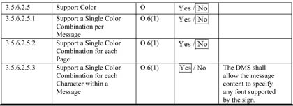
| Item | 4.3.36 |
| Source | IBI Group Final Report – March 30, 2007 |
| Document | NTCIP 1203 DMS v2.25 |
| Page | 55 |
| Paragraph | PRL 2.4.2.3.5 |
| Comment | Some confusion may arise from issues with supplemental requirements being duplicated in the PRL and Supplemental PRL. The PRL may have a specific Supplemental Requirements selected as 'Yes' from an option group but the Supplemental Protocol Requirements List may have all the subclauses for the same option group selected as 'No'. An example of this occurs in the PRL for this project. In the Supplemental PRL, the subclauses of D.3.2 Global Supplemental Requirements are selected as 'No' but in the PRL in User Need ID 2.4.2.3.5 Schedule Messages for Display the requirement ID D.3.2.1 (a subclause of D.3.2) is selected which is contrary to the Supplemental PRL. This could lead to an argument of whether the requirement is required or not. |
| Suggestion | Address ambiguity |
4.6 Minor Typographical Errors
In the course of analyzing the standard, a number of minor editing inconsistencies and errors were found. These items are listed below:
- 5.11.2.3.5.7 Climate-control Test Activation Abortion Paremeter [should be Parameter].
- 5.11.2.9.3.3 to 5.11.2.9.3.7, as well as page 73: Requirement 3.5.6.2.13 and page 74: Requirement 3.5.6.2.13.3 has Celcius instead of Celsius.
- Functional Requirement 3.4.3.1.1.3 in the RTM refers to objects 5.11.2.3.6.6 and 5.11.2.3.6.7 that do not exist. These should reference 5.11.2.3.5.6 and 5.11.2.3.5.7.
- 4.3.1.2 Configure a Font: Step 2: has begining instead of beginning.
- Shutdown Power definition under the glossary of terms has savely instead of safely.
- 5.4.2.7 Font Version ID Parameter has CharacterIinformation instead of CharacterInformation.