
3.0 Testing Process Methodology
3.1 Scope of Test
These tests address the specific observable and testable features of the NTCIP 1203 v2.25 Dynamic Message Signs as it is embodied in the communication protocols of the VDOT procured DMS. The test is not a system acceptance test or stress test, which seeks to compare behavior of the test items to functional or contractual requirements. Rather, this test seeks to compare the usage of the test items to their intended usage described in the standard and identify the reasons for any variations. That said, unlike in previous test activities, the ISTT is leveraging the work of the VDOT/VTTI team who, under a separate USDOT task, completed a comprehensive and thorough acceptance test based on the VDOT-specified PRL requirements. The ISTT examined the results of this testing activity and used it as a basis to determine what additional "exception" testing might be necessary to complete the examination of the implementation per the goals defined below.
Note: The term Testing is used in two distinct contexts in this final report. In general, all work performed with respect to the static analysis, evaluation and interviews and on-site controlled experiments and data gathering of the standards are grouped under the general term Testing. Specifically, the process of performing a set of pre-defined, controlled experiments to acquire data from the deployed system and compare this data to known expected values is also referred to as the onsite Testing phase. Attempts have been made to ensure this distinction is clear in the context of the usage of the term.
3.2 Testing Goals
The overall goal of the ITS Standards Testing Program is to assess and evaluate the 1) suitability, 2) effectiveness, and 3) contribution to interoperability and interchangeability of ITS standards. To best focus on the process to assess and evaluate ITS standards, the test team has identified these three key elements as essential to understanding whether or not a particular standard is ready for field use. These three high-level categorical elements for assessment and evaluation are defined and expanded in the following discussion.
3.2.1 Suitability
The dimension of suitability addresses those aspects of a standard that make it appropriate for a given purpose, easy to understand and use, or the contrary. This also includes issues and measurements relating to a standard's completeness and coverage when defining all aspects of the problem domain and providing access to, and control of, the appropriate technologies. The impact of an unsuitable standard tends to occur early in the system development life-cycle by needlessly complicating or subverting the choice from suitable alternative standards. The evaluation of suitability will be based on quantitative and qualitative analysis of the standards, structured questionnaire responses, and product capabilities, requirements, and design tradeoffs.
3.2.2 Effectiveness
The dimension of effectiveness addresses those aspects of a standard that make its use an appropriate means to achieve the intended or desired effect. This also includes issues relating to how well the features of the standard enable a reasonable and effective implementation in terms of performance requirements and other such operational and maintenance criteria. The impact of an ineffective standard will tend to happen during design and implementation of the system in terms of excessive resource requirements, negative effects on schedule, product performance, etc. The evaluation of effectiveness will be based on quantitative and qualitative analysis of the standards, structured questionnaire responses, operational use, and results from test trials.
3.2.3 Interoperability and Interchangeability
The dimension of interoperability addresses those aspects of a standard that contribute to the ability of systems to provide services to and accept services from other systems and to use the services so exchanged to enable them to operate effectively together. This necessitates that interoperability goes beyond the mere exchange of data and requires that the data exchanged must be usable by the other system. Further, interoperability is extended to interchangeability when characterized by standardized interfaces. The impact of standards that do not contribute positively to interoperability and interchangeability will tend to occur during the integration with other systems. The evaluation of the standards contribution to interoperability and interchangeability will be based on quantitative and qualitative analysis of the standards, logical characteristics of any external interfaces, and detailed examination of the syntactic and semantic content exchanged across those interfaces.
3.3 Testing Process Outline
This section presents an outline of the steps followed in the conduct of the ITS standards testing activities associated with center-to-field device communications standards, of which NTCIP 1203 v2.25 is an example. The test process steps outlined in Table 3.1 describe the effort for determining what data and information would be identified and collected and where and how that collection would be accomplished.
3.4 Establish and Verify Standards Baseline
This step in the process supplements the baseline knowledge of the standards content. It is an essential step to ensure a sufficient and rich standards content baseline that contributes to the decision to proceed with full test planning and conduct. The test team qualitatively and quantitatively verified the degree of use and conformance with the standards of interest. This process included static examination of standards, compilation and examination of any MIB files, and in the case of this specific site, examination of the test plan/procedures, test results, findings, and final reports resulting from the VDOT/VTTI testing activities. This static analysis is the basis for the development of the exception test plan as well as the detailed interview questionnaires.
| Step | Description | Expected Outcome |
|---|---|---|
| Baseline Standards Content |
|
|
| Interview Users, Vendors, and System Integrators |
|
|
| Evaluate the Purity and Integrity of the External Interfaces |
|
|
| Conduct Exception Testing |
|
|
VDOT provided a robust package of documentation, specifications, and data as it related to their implementation of the DMS standard. Specifically, this included the results of all testing completed against the sign and the management station software, as well as final reports from the vendor, test developer, and test conductor. This documentation was examined and compared with the standards to determine percentage of coverage, extract any findings for further examination, and identify any exceptions or customizations to the standards.
Three important result sets were generated as part of this analysis:
- Diagram showing all of the objects contained within the standard and the grouping used for these objects.
- Narrative comments, which will be included in the final report, were also preserved in electronic format.
- Relational database, which captured all of the features of the standard and how these different items related to one another.
The first two results were used to better understand and document the standard and findings. The third item, the relational database, was used to generate the test cases for the test plan. In order to facilitate the analysis and test case creation, the ISTT performed the following:
- Created a database, which captured features and relationship of features within the standard.
- Annotated each object and functional requirement in the database as follows:
- Testable – Indicates whether the feature was testable or organizational. For a functional requirement (FR), this meant the FR was not a high-level 'wrapper', but instead, had a direct relationship to interfaces, dialogs, and ultimately, objects.
- Tested Status – Indicates whether the feature was tested as part of the VDOT/VTTI test activities.
- Result – Identified those which failed the VDOT/VTTI testing activities.
- Test Criteria – This indicates the valid values, ranges, or contents for a given object.
- Generated from this database the following items:
- List of failed FRs and their associated objects.
- List of all objects including syntax, access (read-only, read/write, etc.), status (mandatory/optional) and the valid and invalid ranges.
- List of testable dialogs.
The lists generated from the database analysis were then used to create the coverage statistics listed in Section 3.6 of this report and to generate the test cases for the controlled testing as described in Appendix B of this report.
The results of this analysis indicated that, with the exception of some findings documented in both the VDOT final report and herein, the VDOT deployment strongly adheres to the ITS standards and shows both a commitment to use of the features of the standards as defined in the standard as well as the success in using standards to integrate separately developed components into a functional system, which satisfies the end-user functional requirements with minimal post-development adjustments.
3.5 DMS Standard Coverage
When considering percentage of coverage, it should be noted that the DMS standard covers a variety of different physical types of message signs and that in actual implementation and operational use, it is recognized that most agencies would procure only a specific sign type, and as such, certain functional and supplemental requirements and their subordinate dialogs, interfaces, and objects are used more often and contribute more value to functionality to an agency than others. In the case of the VDOT deployment, the sign is of a type full-matrix Dynamic Message Sign and with the exception of the exclusion of the more-complex graphical capabilities, the VDOT implementation includes and exercises most of the features considered basic to this form of sign.
Table 3.2 identifies the total quantity of each of the features of the NTCIP 1203 standard as well as the total quantity of each feature type implemented by VDOT. Coverage percentages for the standard consider the total number of features in each of the different areas, but focuses on satisfying user needs and functional requirements. As seen in the table below, nearly three-fourths of the user needs identified in the standard were implemented by the VDOT deployment. Even more illustrative of the robustness of this test, 87% of the functional requirements specified in the standard were used in the VDOT deployment. This resulted in equally large percentages of the other key features, dialogs and interfaces, covered by the deployment at 88 and 91% respectively, to exist.
| NTCIP 1203 Features | Clauses | Total in NTCIP 1203 v2.25 | Total Used by VDOT | Coverage |
|---|---|---|---|---|
| User Needs | 2.3.2.x, 2.4.1.x-2.4.3.x | 32 | 23 | 72% |
| Functional Rqmts. | 3.3.x.x, 3.4.1.x - 3.4.3.x | 122 | 106 | 87% |
| Supplemental Rqmts. | 3.5.x | 84 | 56 | 67% |
| Dialogs | 4.3.1.x - 4.3.3.x | 33 | 29 | 88% |
| Interfaces | 4.4.1.x-4.4.12.x | 122 | 111 | 91% |
| Objects | 5.x | 233 | 195 | 84% |
Table 3.3 indicates similar coverage percentages for the features of the NTCIP 1201 Global Object standard that are included in Appendix D of the DMS standard. Similar to the coverage statistics cited above, nearly all of the Global Objects features identified in this normative reference, where covered by the VDOT deployed functional requirements.
| NTCIP 1201 Global Features included in NTCIP 1203 | Clauses | Total in NTCIP 1203 v2.25 | Total Used by VDOT | Coverage |
|---|---|---|---|---|
| User Needs | N/A | |||
| Functional Rqmts. | D.3.1.x | 8 | 7 | 88% |
| Supplemental Rqmts. | D.2.3.x | 11 | Not calculated | |
| Dialogs | D.4.1.x-D.4.2.x | 5 | 5 | 100% |
| Interfaces | D.4.3.x-D.4.5.x | 22 | 22 | 100% |
| Objects | Not included in NTCIP 1203 Std. | |||
3.6 Participation of VDOT Test Activities
ISTT team members, as outlined in Subtask 4 of the SOW, participated in test sessions held at the VTTI facility in Blacksburg, VA over the period of approximately two months during the winter of 2007.
While attending these test sessions, the ISTT met with each of the partners on a daily basis and was granted access to all meetings, test results, etc. and was aware of all successes, issues, and discussion items. In addition to the face-to-face interaction, the ISTT also ensured that the stated work items under this Subtask, as shown below, were met. The approach to meeting each of these work items is also included.
- Arrival and instrumentation at test site – The ISTT will arrive on site at VTTI on a pre-established date based on VDOT's schedule. The ISTT will work with the VDOT and VTTI communications engineers and staff to establish the "test environment" and attach test measurement and diagnostic equipment to ensure that the data are being captured.
Approach: The VDOT/VTTI/Trevilon test team implemented a combination of the FTS for NTCIP packet capture /analysis tool, utilized the logging features of the NTester test tool, utilized Adobe Captivate to capture screen actions, and also captured test notes in a database. This satisfied all of the ISTT needs for data capture for subsequent analysis. - Monitor functional and interface testing – The ISTT will monitor the tests performed by the VDOT team as per the finalized test plans and will be available for support and assistance as necessary.
Approach: A member or members of the ISTT were in attendance for a majority of the testing conducted against both the controller and the management station software and responded to any inquiries during these visits. - Conduct interviews – The ISTT will also perform interviews with stakeholders to collect subjective data for consideration in the recommendations made for the standard. Interviews will be conducted with vendors, deployers, and operations personnel, as appropriate.
Approach: Battelle determined that the best timing on these interviews was to await each partner's final report and to then develop and conduct the interview questionnaire with each partner. The results of these interviews are summarized in Section 3.8 below. - Data collection, reduction, preliminary analysis – At the end of each day of testing, the ISTT will record test results and observations on forms specifically designed for these purposes. These collected written data will be copied and then forwarded to an off-site facility where they will be entered into the test repository. This repository will be used in the subsequent reduction and analysis of the test results.
Approach: The ISTT maintained individual notes and were provided daily results from the VDOT team. The ISTT also received a copy of the VDOT DMS Testing Final Report, which included all of the captured test data and each partner's final report and utilized this information as the basis of the examination and exception test cases.
3.7 Interview Product Vendor/Developers
This step includes structured technical interviews conducted with each of the major stakeholders associated with the deployment. For this deployment, the list included the public agency representative, the sign vendor, the management station vendor, and the deployment lead. Table 3.4 identifies the individual, their role, and the organization they represent.
| Role | Contact | Organization |
|---|---|---|
| Public Sector | Ashwin Amanna | VTTI |
| Test Integrator | Ken Vaughn | Trevilon Corp |
| Sign Vendor | Milan Patel | LEDStar, Inc. |
| Management Station | Richard Chang | IBI Group |
Interview questionnaires were prepared in advance and were derived from the static examination of the standard and each party's contribution to the VDOT Final Report. Although the questionnaires primarily consist of questions related to the results of the acceptance testing activities, it also includes questions directed to the vender's implementation of the standards. These interviews aid in the understanding of the vender's implementation and address at least three potential categories of issues:
- Issues related to exceptional conditions discovered by the developer.
- Subjective and qualitative coverage and data collection for assessment of non-testable technical features.
- Verification of standards content baseline prior to the commitment of resources to the more specific and extensive field testing.
The interview questionnaires were conducted via telephone over the period of eight days starting July 27, 2007. Each of the above contacts was asked both subjective and objective questions related to their overall impression of the standard and its suitability, effectiveness, and contribution to interoperability and interchangeability. There were also asked specific questions related to their findings. The text of the questionnaire, along with the responses from the various participants, is included in Appendix A of this document.
Upon completion of these interviews, the results were compiled and reviewed and any additional findings documented. These findings, both general and specific, are described in Section 4.0 of this report.
3.8 Evaluate the Purity and Integrity of the External Interfaces
This step in the testing process was designed to examine the external interfaces employed in the system to determine that all communications and protocols used were consistent in terms of syntax and semantic content, and that there is no unexplained communications activity on the SNMP interface.
The test team used both the vendor-provided Management Station software (which is based on the NTCIP Exerciser v2.0) and Intelligent Device's DeviceTester for NTCIP software (hereafter referred to as the Test Tool) to exercise and interrogate the features of the standard. The interactions where captured and examined using FTS for NTCIP. Figure 3.1 shows how the test environment was configured. The results of this examination revealed no exceptions or concerns and the protocols used and information exchanged was as expected.
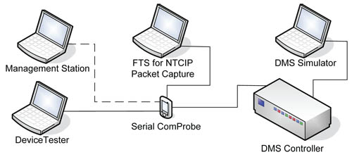
Figure 3.1. Test Configuration
This step proved to be an important confidence builder in that it was a successful test of the ability to communicate between the sign-controller, the test software, and the protocol analyzer and served to reduce risk and eliminate distractions prior to conducting the exception testing.
3.9 Conduct Exception Testing
This is the final step in the testing process and is designed to collect empirical data through exercise and observations of the testable features of the standards embodied in the deployed system. The DMS test plan is comprised of three components:
- Experimentation/Validation of Specific Findings – For each object associated with a failed functional requirement, as identified in the VDOT Final Report, the ISTT conducted a series of trials associated with the object. These trails varied, depending on the object type, but typically consisted of confirming/denying implementation, accessibility, and valid use (i.e. ranges, string information, etc.).
- Controlled Testing of Objects – For each object included in the standards, the ISTT determined, depending on the type of object, the possible test criteria and using both automated means available through the Test Tool software, as well as manually setting/interrogating the objects through either Test Tool or the Management Station, the ISTT tested both normal conditions and abnormal conditions.
- Controlled Testing of Dialogs – Using the list of dialogs as documented in Section 3.11 below, the ISTT examined the implementation as provided by the Management Station software, as well as performed, using the steps provided in the standard, the same dialogs via the Test Tool interface in order to determine if any findings existed.
The specifics of these three components of test are outlined in the test plan.
3.10 Test Approach
The test environment consisted of three laptops computers, the sign controller, a serial data sniffer (ComProbe), the Test Tool software, the Management Station Software, FTS for NTCIP software, the sign simulator, and the necessary cables to interconnect the systems. Both Test Tool and the Management Station Software were installed on the same laptop and were used as indicated in the test plan.1 The equipment was interconnected as shown in Figure 3.1 above.
This setup is physically similar to the setup used during the VDOT testing; however, several of the software components have been replaced with different, but equivalently functioning test tools. All of the test cases utilized the Test Tool software to both exercise and interrogate the objects and dialogs included in the test plan. As part of the testing of the dialogs, however, both the Test Tool and the Management Station software tools were utilized. The image in Figure 3.2 depicts the actual test system.
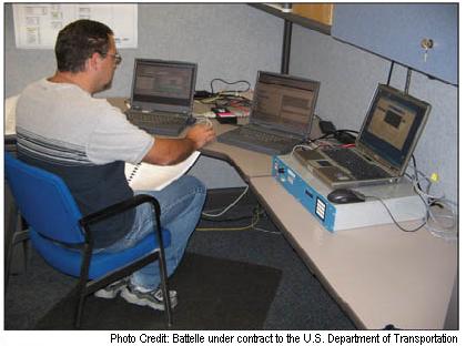
Figure 3.2. DMS Test System
Experimentation/Validation of Specific Findings – As part of the review of the VDOT Final Test Report, the ISTT extracted a list of the failed functional requirements and further investigated to determine the specific objects that caused the failure. This list is shown in Table 3.5. Each of these objects was exercised through a series of ad-hoc experiments. Any findings associated with this testing are documented in Section 4.0.
| Functional Requirement | FR ID | Paragraph | Object |
|---|---|---|---|
| Determine Number of Trigger Events | 3.4.2.3.12.2 | 5.7.27.1 | eventControlMaxTriggers |
| Determine Number of Trigger Events | 3.4.2.3.12.2 | 5.7.27.2 | eventControlNumTriggers |
| Execute Climate-Control Equipment Testing | 3.4.3.1.1.3 | 5.11.2.3.6.6 | dmsClimateCtrlTestActivation |
| Execute Climate-Control Equipment Testing | 3.4.3.1.1.3 | 5.11.2.3.6.7 | dmsClimateCtrlAbortReason |
| Monitor Power Error Details | 3.4.3.1.4.1 | 5.11.2.2.3.1 | dmsPowerIndex |
| Monitor Power Error Details | 3.4.3.1.4.1 | 5.11.2.2.3.2 | dmsPowerDescription |
| Monitor Power Error Details | 3.4.3.1.4.1 | 5.11.2.2.3.3 | dmsPowerMfrStatus |
| Monitor Power Error Details | 3.4.3.1.4.1 | 5.11.2.2.3.4 | dmsPowerStatus |
| Monitor Power Error Details | 3.4.3.1.4.1 | 5.11.2.2.3.5 | dmsPowerType |
| Monitor Power Errors | 3.4.3.1.3.1 | 5.11.2.2.1 | dmsPowerStatusMap |
| Monitor Power Errors | 3.4.3.1.3.1 | 5.11.2.2.2 | dmsPowerNumRows |
Controlled Testing of each Object – For each test case included in the test plan, the appropriate object ID (OID) was selected in the Test Tool and was either read or a value was attempted to be set and the results of the operation recorded. Additionally, the Test Tool itself maintained a log of activities, which was used as part of the post-test analysis. The completed test cases are included in Appendix B and are recorded on the companion CD accompanying this report. Any findings associated with these test cases are included in Section 4.0.
The valid conditions that were exercised by the testing for each object included:
- Assurance that all implemented objects can be accessed
- Assurance that all writeable objects can be set to specified min and max values
In addition to the valid states, each object was subjected to conditions which would be considered outside of the normal operating range, or in other words, intentionally presenting values which are expected to result in an error condition. The invalid conditions that each object was subjected to include:
- Attempt to write to read-only objects
- Attempt to read non-accessible objects
- Setting object values to out-of-range conditions
Controlled Testing of Dialogs – The ISTT selected a sample of passive dialogs defined by the standard, as well as those implemented by the management station and conducted controlled experiments for each. Table 3.6 shows which dialogs were tested and how they were exercised. Some of the dialogs defined by the standard were not valid as noted in the findings section of this report.
| ID | Name | Tested | Mgmt Station | Device Tester | Disposition |
|---|---|---|---|---|---|
| 4.3.1 | Manage the DMS Configuration | ||||
| 4.3.1.1 | Retrieve a Font Definition | Yes | ● | passed | |
| 4.3.1.2 | Configure a Font | No | non-passive | ||
| 4.3.1.3 | Delete a Font | No | non-passive | ||
| 4.3.1.4 | Validate a Font | Yes | ● | passed | |
| 4.3.1.5 | Retrieve a Graphic Definition | Yes | ● | passed | |
| 4.3.1.6 | Store a Graphic Definition | Yes | ● | passed | |
| 4.3.1.7 | Delete a Graphic | Yes | ● | passed | |
| 4.3.1.8 | Validate a Graphic | Yes | ● | passed | |
| 4.3.1.9 | Configure Light Output Algorithm | Yes | ● | passed | |
| 4.3.2 | Control the DMS | ||||
| 4.3.2.1 | Activate a Message | Yes | ● | ● | passed |
| 4.3.2.2 | Define a Message | Yes | ● | ● | passed |
| 4.3.2.3 | Retrieve a Message | Yes | ● | ● | passed |
| 4.3.2.4 | Define a Schedule | No | |||
| 4.3.2.5 | Configure Messages Activated by Non-Standard Events | No | |||
| 4.3.2.6 | Define a User-Defined Event | No | |||
| 4.3.2.7 | Manually Control Brightness | Yes | ● | passed | |
| 4.3.2.8 | Manage the Exercise of Pixels | No | |||
| 4.3.2.9 | Activate a Message with Status | No | |||
| 4.3.3 | Monitor the Status of the DMS | ||||
| 4.3.3.1 | Execute Lamp Testing | No | not implemented | ||
| 4.3.3.2 | Execute Pixel Testing | No | invalid | ||
| 4.3.3.3 | Execute Climate-Control Equipment Testing | No | |||
| 4.3.3.4 | Monitor Power Error Details | Yes | ● | passed | |
| 4.3.3.5 | Monitor Lamp Error Details | No | not implemented | ||
| 4.3.3.6 | Monitor Pixel Error Details | No | |||
| 4.3.3.7 | Monitor Light Sensor Error Details | Yes | ● | passed | |
| 4.3.3.8 | Monitor Message Activation Error Details | Yes | ● | passed | |
| 4.3.3.9 | Monitor Climate-Control System Error Details | No | |||
| 4.3.3.10 | Monitor Sign Housing Humidity | No | invalid | ||
| 4.3.3.11 | Monitor Control Cabinet Humidity | No | |||
| 4.3.3.12 | Monitor Drum Sign Rotor Error Details | No | not implemented | ||
| 4.3.3.13 | Monitor Attached Devices | No | |||
| 4.3.3.14 | Monitor the Current Message | No | |||
| 4.3.3.15 | Monitor Dynamic Field Values | No |
3.11 Test Results
The controlled testing was carried out over a period of two weeks in August 2007 using the setup described previously and as shown in Figure 3.1. All the test cases described in Appendix B were performed. For each test case, the following eight steps were performed.
- Read the data object's initial value
- Set the data object to its minimum value and read it
- Set the data object to its maximum value and read it
- Attempt to write to a read-only data object
- Attempt to read a non-accessible data object
- Attempt to set the data object to a value grater than its maximum value
- Attempt to set the data object to a value less than its maximum value
- Restore the data object's original value
Testing Notes
- The reading of the initial value of each data object validates that the object was implemented and provides the data necessary to restore the object at the conclusion of the testing.
- Validating the implemented range of each data object was performed by setting its minimum and maximum values and reading back the object to determine if the range was accepted. This step was skipped for objects that are designated as read-only resulting in the read-back value to be unchanged from its initial value.
- The attempts to exercise a data object using invalid operations or value range were skipped if the test did not represent an invalid operation.
- The test results of this testing were captured and stored in a database that resides on the companion CD that accompanies this report. When filtering the captured data to show only those object identifiers (OID) that represent an actual data object, the result metrics summarized in Table 3.7, were realized.
| Number of Tested OIDs | Total Number Records Logged During Test |
|---|---|
| 390 | 3,083 |