
3.0 Results of Overall Surveillance and Detection Needs Analysis from Phase 1 of the ICM Initiative
The analysis of the overall surveillance and detection needs for the ICMS operational concepts started with a review of the operational concepts, specifications, and training documents for the ICM Initiative. These include:
- The ICMS Concept of Operations for a Generic Corridor [United States Department of Transportation. Integrated Corridor Management – Concept Development and Foundational Research, Task 2.3 – ICMS Concept of Operations for a Generic Corridor. Washington DC: ITS Joint Program Office, 2006.]
- The ICMS Foundational Research on Corridor Management Strategies [United States Department of Transportation. Integrated Corridor Management, Phase 1 – Concept Development and Foundational Research, Task 5.4 – Identify ICM Approaches and Strategy – Asset Needs and Integration Issues, Technical Memorandum, FHWA-JPO-06-040, EDL #14279. Washington DC: ITS Joint Program Office, 2006.]
- The ICMS Surveillance and Detection Needs Analysis [United States Department of Transportation. Integrated Corridor Management Technical Integration, ICMS Surveillance and Detection Needs Analysis. Washington, DC: ITS Joint Program Office, 2007.]
- The ICMS Concept of Operations documents from each pioneer site [PATH: University of California at Berkeley. Interstate 880 Integrated Corridor Management (Oakland, California) Final Concept of Operations. Washington DC: US Department of Transportation, 2008.] [Dallas Area Rapid Transit. Concept of Operations for the US-75 integrated Corridor in Dallas, TX. Washington DC: US Department of Transportation, 2008.] [Maryland Department of Transportation. Integrated Corridor Management Program – Maryland I-270 Corridor – Concept of Operations – Stage 1 Final. Washington DC: US Department of Transportation, 2008.] [Minnesota Department of Transportation. Minnesota – I-394 Corridor Integrated Corridor Management – Concept of Operations – Final. St. Paul: Minnesota Department of Transportation, 2008.] [San Diego Association of Governments (SANDAG). San Diego I-15 Integrated Corridor Management System – Final Concept of Operations. San Diego, CA: SANDAG, 2008.] [Southwest Research Institute. TransGuideTM Integrated Corridor Management Concept of Operations – Version 1.0.2. San Antonio: Texas Department of Transportation, 2008.] [Washington State Department of Transportation. Seattle ICMS Concept of Operations. Seattle, WA: Washington State Department of Transportation, 2007.]
- The ICMS System Requirements Specifications from each pioneer site [PATH: University of California at Berkeley. Interstate 880 Integrated Corridor Management (Oakland, California) Final System Requirements. Washington DC: US Department of Transportation, 2008.] [Dallas Area Rapid Transit. High Level Requirements for the US-75 integrated Corridor in Dallas, TX. Washington DC: US Department of Transportation, 2008.] [Maryland Department of Transportation. Integrated Corridor Management Program – Maryland I-270 Corridor – System Requirements Specification – Stage 1 Final. Washington DC: US Department of Transportation, 2008.] [Minnesota Department of Transportation. Minnesota – I-394 Corridor Integrated Corridor Management System (ICMS) – System Requirement Specification. St. Paul: Minnesota Department of Transportation, 2008.] [San Diego Association of Governments (SANDAG). San Diego I-15 Integrated Corridor Management System – Final I-15 ICM System Requirements. San Diego, CA: SANDAG, 2008.] [Southwest Research Institute. TransGuideTM Integrated Corridor Management Requirements Specification Document – Version 1.0.0. San Antonio: Texas Department of Transportation, 2008.] [Washington State Department of Transportation. Seattle ICMS Requirements. Seattle WA: Washington State Department of Transportation, 2008.]
- The Traffic Control Systems Handbook [Gordon, Robert L., Robert A. Reiss, Herman Haenel, E. Ryseron Case, Robert L. French, Abbas Mohaddes, and Ronald Wolcott. Traffic Control Systems Handbook. Washington, DC: Federal Highway Administration, 1996.]
3.1 An Example Scenario
The following incident scenario provides an example of how ICM concepts might function in a corridor to coordinate operations within the corridor and enhance the movement of goods and people through the corridor.
In the following scenario, the Freeway Management System (FMS), Arterial Management System (AMS), Transit Management System (TMS), and Public Safety System (PSS) share information about the situation that is essential for making decisions about the incidents. Once the decisions are made, the chosen response must be implemented and information must continue to flow between participants to support the response.
Scenario:
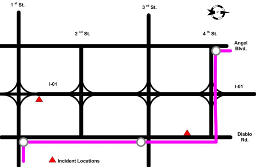
This scenario is based on an incident on Northbound I-01 between 1st and 2nd street interchanges, and at the same time, an incident on Southbound Diablo Rd. between 3rd and 4th Street. Either or both of these incidents could affect the transit "Purple Route" which runs an express every 30 minutes and a local at a 15 minute delay between express runs. Figure 3 shows the corridor and the locations of the incidents.
 >
>
ICM Decisions:
The ICM operations personnel will need to collect information about the situation and make some decisions about what should be done. The decisions might include the following:
- Should some freeway traffic be diverted off I-01 to Angel/Diablo arterials between 1st and 2nd St. interchanges?
- Should some arterial traffic be diverted off Diablo Rd. to Angel/I-01 at 3rd and 4th St.?
- Should Purple Route buses be re-routed or assisted around problem areas?
- What information should be given to the public?
- What assistance can be provided to public safety?
To answer these questions and make the associated decisions, some of the information in the following table will be needed by the operations staff and decision support systems. The table shows the possible information sources and who might need the information.
Initial Information Needs:
From |
To Freeway Operations |
To Arterial Operations |
To Transit Operations |
To Traveling Public |
To Public Safety |
|---|---|---|---|---|---|
FMS |
|
|
|
|
|
AMS |
|
|
|
|
|
TMS |
Not Applicable |
|
|
|
Not Applicable |
PSS |
|
|
|
Not Applicable |
|
Decisions made:
Based on the severity and expected duration of the incidents, some action will be appropriate. The decision support systems provide information to the operations staff, allowing the following decisions to be made:
- Capacity Northbound on the arterials is enough to allow light vehicles to be detoured around the freeway incident. Drivers on the interstate will be notified of the incident and advised to try Angel/Diablo diversions.
- Capacity Southbound on the freeway and Angel Blvd is enough to allow Diablo Rd traffic to divert to these alternate routes to avoid the arterial incident. Drivers on Diablo will be notified of the incident and advised to try Angel Blvd or I-01 as alternate routes.
- Signal timing along Angel/Diablo routes between 1st and 2nd will be modified to enhance additional traffic flow from the freeway detour.
- Ramp metering system (RMS) timing will be modified to allow traffic onto the freeway at appropriate interchanges for both the I-01 and Diablo Rd diversions. Signal timing at appropriate off-ramps will be modified to allow a higher volume of traffic to exit the freeway.
- The transit express route can be diverted away from both incidents. Local route transit vehicles will run as scheduled, but may require signal priority at some intersections to keep on schedule.
- Public safety crews will be dispatched to both incidents along the best available routes, but may require signal priority at some/all intersections.
Follow-up Information/Coordination Needs:
Implementing the above plan will require a coordinated effort and continued information flow between the participating agencies and notifications to the traveling public.
From |
To Freeway Operations |
To Arterial Operations |
To Transit Operations |
To Traveling Public |
To Public Safety |
|---|---|---|---|---|---|
FMS |
|
|
Not Applicable |
|
|
AMS |
|
|
|
|
|
TMS |
Not Applicable |
|
|
|
Not Applicable |
PSS |
Not Applicable |
|
Not Applicable |
Not Applicable |
|
3.2 Surveillance and Detection Needs
Appendix C includes twenty need statements that reflect the general set of needs for an ICMS based on this review. The following needs represent the key elements of an ICMS deployment that are impacted by gaps in the arterial data:
- Need to understand demand for transportation services (1.2)
- Need for corridor performance measures (1.2.1)
- Need for impact assessment tools (1.2.2)
- Need to collect information about performance and response of the transportation network (1.2.2.1)
These generic needs point to the kinds of surveillance and detection considered necessary for the corridor management activities. Data is needed to measure or calculate performance measures for the transportation services, and data is needed for modeling the transportation services to help operators understand how the transportation systems will respond to the control actions they may undertake.
Appendix D includes thirty-one detailed needs that were identified in the ICMS Surveillance and Detection Needs Analysis [United States Department of Transportation. Integrated Corridor Management Technical Integration, ICMS Surveillance and Detection Needs Analysis. Washington, DC: ITS Joint Program Office, 2007]. These detailed needs were summarized as:
- Needs related to general ICM characteristics
- Needs related to ICM approaches
- Needs related to ICM strategies
- Needs related to ICM operational data
Analysis of the needs, current methods, and typical data sources indicates that surveillance and detection data must support calculation of current performance of a transportation mode and comparison with the design or ideal performance of the transportation mode being monitored. The system must also be able to identify trends within the data being monitored.
Data needs will vary based on the ICM strategies, the infrastructure within the corridor, the participating agencies, and the types of analysis, modeling, and decision support tools that are implemented. There is no strong consensus at this time about what data is actually needed from arterial systems for ICM implementation. The consensus is equally poor about what performance measures for arterial systems are critical for corridor management.
This is a new operational territory and it may well turn out that the data and performance measures for corridor operations are different from the traditional data and measures used for operation of arterial traffic signal systems.
Appendix E provides a preliminary list of data needs for ICM contrasted with typical data capabilities for operation and planning based on standard operating procedures.
3.3 Current Surveillance and Detection Capabilities
Surveillance and detection measurements for individual transportation modes are generally based on the control needs for managing the systems without regard to impact on other transportation modes. Additional data is collected based on requirements for reporting to local, state, or federal transportation agencies. The following values are typically monitored (although not necessarily in real-time):
Freeway/Tollway Monitoring:
- Road segment speed (average vehicle distance traveled/time unit) – current and by time of day
- Road segment volume (vehicles/time unit) – current and by time of day
- Road segment occupancy (% of unit length lane occupied by vehicles) – current and by time of day
Transit Monitoring:
- Volume (passengers/route leg) – by time of day and day of week
- Fare collected/route leg – by time of day and day of week
- Schedule adherence (difference between vehicle actual arrival/departure and scheduled arrival/departure) – current and daily summary/route
Parking Management Monitoring:
- Volume (number of vehicles using the parking facility) – current and daily total
- Parking spaces remaining – current
Arterial Monitoring:
- Call (vehicle/pedestrian presence)
- Volume (number of vehicles passing a point on the roadway during a specified time period) – current average per unit time and by time of day
- Road segment occupancy (percent of time that a point on the roadway is occupied by a vehicle) – current average per unit time
- Road segment speed (distance traveled by a vehicle per unit time) – current average
- Queue length (number of vehicles stopped in a lane behind the stop line at a traffic signal) – current calculated count
- Headway (time difference between beginning of successive vehicle detections) – current average
It should be noted that in the above list of data monitored, the performance measures that are reported are not generally the values that are used to manage the performance of the transportation modes. For example: volumes are reported on highways, but speed and occupancy are the values used for responsive ramp metering. Passenger volume is reported on transit systems, but current schedule adherence values are the measurements used to control transit signal priority and to make real-time decisions about schedule and route deviations. Daily volume is reported for parking facilities, but signs and access controls are driven off of the number of spaces remaining. Arterial reporting is primarily based on volume and level of service (speed), but local signal controls use call, density, calculated delay, and queue length for the primary control parameters.
3.4 Arterial Signal System Capabilities
As previously noted, an initial premise of this Needs Analysis was that the existing signal control infrastructure may support the arterial data needs for an ICMS. However, some caution should be exercised when discussing the capabilities of arterial signal systems. The state-of-the-art and the state-of-the-practice in any given location may differ greatly. A corridor may include multiple signal systems operated by individual municipal, county, or state jurisdictions. While larger, wealthier jurisdictions may have modern state-of-the-art signal systems; other jurisdictions may have older, even antiquated signal systems.
A modern signal system typically comprises a central server with real-time connectivity to signal controllers at the intersections. Signal systems may control traffic along large arterial corridors or across an entire municipality. In recent years, some systems have been deployed that span multiple jurisdictions and provide coordinated signal control across an entire region. Centralized systems can often support a range of management strategies; ranging from simple monitoring, to active control of signal timing plans, to real-time adaptive signal timing.
Loop detectors used in signal systems are now being replaced more frequently with non-intrusive detectors, such as RADAR or CCTV sensors. While many deployments still use a contact closure from these sensors to signal vehicle presence to the controller, the sensors may support data interfaces capable of reporting additional information, such as speed, volume counts, and occupancy.
In addition to the broadband communication interfaces needed for coordinated control, newer controllers may also have faster processors and more memory. These additional capabilities allow controllers to be programmed to collect and report additional traffic data to their central systems. Many newer devices also support the standard NTCIP protocol for communication with signal controllers. At least three manufacturers currently support an extension of the NTCIP protocol that allows for the collection and reporting of additional data required for adaptive signal systems.
It is becoming more common for newer signal control systems to support data interfaces that allow some traffic information to be shared with other external systems. However, full, bi-directional, center-to-center data exchange interfaces are less common, and, where they exist, are usually the result of site specific requirements rather than a standard product offering.
3.5 Identifiable Gaps
Essentially, the substantial majority of the existing traffic controllers in the US use the same basic structure of cyclic operation, splits, rings, barriers, phases, and overlap information. This information usually comes to the controller in the form of discrete contact closures from a roadway sensor, although a growing number of microwave and video detection systems are capable of providing additional data through serial data interfaces. However, most signal systems are unable to accept the data in this format.
The majority of the status information received is used locally by the controller and then discarded. Memory limitations in the controllers and limited bandwidth for communications links are cited as the primary cause for data deficiencies from the controllers to central systems. Some forms of summary statistics for both phase operation and detector operation are typically available on most traffic controllers, but manufacturers usually implement an averaging mechanism in the controller firmware to conserve memory. Typical implementations provide access to 5-minute or 15-minute averages of traffic volume data for detectors and phase duration data.
Newer systems support centralized collection of phase and detector performance, alarm, and diagnostic information, with update times limited only by the inherent latency of the data collection and communications systems. However, without firmware modifications, these systems are still collecting averaged data rather than real-time data.