
3.0 Performance Measures and Analysis Approach
The AMS methodology includes the capability to convert all impact/performance measures to non-mode specific measures such as person trips. These mode-independent performance measures will be produced by an interface tool that can translate AMS model components outputs into non-mode-specific performance measure output. Since ICM is multimodal, the operational impacts need to be measures beyond the traditional network-based measures. The AMS framework outputs will be converted to performance measures, such as person travel time or trip reliability, in order to evaluate and compare operations among the alternative paths and properly portray the collective corridor-wide performance.
The AMS methodology is flexible enough to accommodate the analysis needs of corridors in a range of urban areas across the nation. For example, corridors in the nation’s largest metropolitan areas may have broad and complex corridors served by multiple layers of transit operations. Corridors in smaller or developing markets may have simpler corridors with more limited transit operations. Certain types of analysis may not be relevant in particular jurisdictions, just as complex feedback between classes of analytical models may not be required in some corridors.
The performance and benefit-cost framework outlined in this chapter establishes traffic analysis goals and objectives; and sets expectations, needs, and issues related to the corridor study analysis performance measures, expected output, and project prioritization/cost-benefit requirements. The following objectives of this framework are to ensure that performance measures and analysis methods:
- Are consistent across different types of corridors, such as the ones described above;
- Are consistent across levels of analysis, including existing/future for short-and long-term strategies;
- Are consistent across different transportation modes; and
- Take into account recurrent and non-recurrent congestion.
This chapter presents:
- A list of recommended performance measures for use in ICM AMS;
- A framework to enable a consistent assessment of existing conditions, application of performance measures, and analysis considerations;
- An output format for the ICM AMS corridor studies; and
- A prioritization/cost-benefit framework.
3.1 Corridor Analysis Approach
Figure 3.1 provides an overview of the ICM AMS corridor analysis approach. It describes the process that should be followed in the AMS of Pioneer Site corridors.
Figure 3.1 Overview of the ICM AMS Analysis Approach
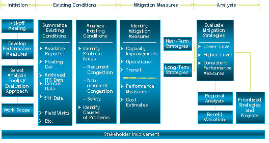
The following steps are involved in this process:
- Kickoff meeting – In this meeting, the analysis team will establish communication channels, protocols, and data and information sources; discuss the scope of work, schedule, and budget; and obtain a thorough understanding of the goals for the analysis. Also in this meeting, appropriate performance measures and analysis tools will be selected for the corridor.
- Data collection and analysis of existing conditions – In this step, the analysis team will collect and analyze all information necessary to understand existing traffic conditions in the study area, and identify specific causes of problems. Data include the following:
- Geometric data – Number of lanes on the freeway and parallel arterials; and basic geometric information, such as lane and shoulder widths, transit service, and configurations of key intersections on parallel arterials.
- Existing traffic performance data for all modes, including peak-period traffic volumes on the freeway and parallel arterials, vehicle occupancies, truck percentages, transit ridership, congestion data, delay data, travel time data, and accident and incident data.
- Information from corridor studies currently underway or recently completed to compile a list of projects and strategies that have been planned or programmed.
- A field review of each travel mode within the study corridor.
The data will be analyzed to determine causes of existing recurrent traffic congestion problems in the corridor. Locations of freeway bottlenecks will be identified, as well as other locations that may constitute mobility constraints in the corridor, such as freeway ramps or arterial intersections. The data also will be analyzed to quantify the magnitude of non-recurrent congestion in the corridor. The results of the existing conditions analyses will be summarized in an Existing Conditions Technical (ECT) memorandum. At a minimum, the ECT memorandum will include a description of the roadway and transit network, including a map showing the corridor study network; and a detailed description of existing traffic performance on the corridor with specific explanations of the causes of congestion problems.
Develop ICM strategies and projects – In this step, the analysis team will refine the ICM strategies developed for the corridor. The proposed strategies will be segregated into short- and long-term implementation timelines, consistent with the Concept of Operations documents developed at Pioneer Sites. For the identified mitigation strategies, the analysis team will develop performance measures and prepare planning-level cost estimates. The list of strategies and projects then will be summarized in a technical memorandum.
Evaluation of congestion mitigation strategies and projects – In this step, the analysis team will evaluate the ICM strategies and projects making use of AMS framework described in previous chapters. The analysis is intended to identify locations of freeway bottlenecks, changes in aggregate congestion levels in the corridor, and changes in peak-period travel times and delays. Based on the analysis, a prioritized list of recommended measures will be developed, including a narrative explaining the rationale for the prioritization. A technical memorandum will be produced summarizing the results of the analysis; and a prioritized list of ICM strategies, including recommendations for any modifications to proposed projects and strategies.
3.2 Performance Measures
This section provides details on the proposed performance measures to be used in the evaluation of ICM strategies. To be able to compare different investments within a corridor, a consistent set of performance measures should be used.
The following are primary objectives of the proposed performance measures:
- Provide an understanding of existing traffic conditions in the study area;
- Demonstrate the ability of ICM strategies to improve corridor mobility, throughput, reliability, and safety based on current and future conditions;
- Prioritize individual investments or investment packages within a given corridor for short- and long-term implementation; and
- Prioritize individual investments or investment packages among corridors based on cost-effectiveness and benefits to the corridor.
As much as is feasible, the primary performance measures should be reported for existing and future conditions, and should be easily calculated to evaluate any proposed improvement scenarios. To the extent possible, the measures should be reported by:
- Mode – Single-Occupancy Vehicles (SOV), High-Occupancy Vehicles (HOV), transit, freight, etc.;
- Facility type – Freeway, expressway, arterial, local streets, etc.;
- Jurisdiction – Region, county, city, neighborhood;
- Corridor-wide; and
- Peak-periods and by hour of the day.
The proposed performance measures focus on the following four key areas:
- Mobility – Describes how well the corridor moves people and freight;
- Reliability – Captures the relative predictability of the public’s travel time; and,
- Safety – Captures the safety characteristics in the corridor, including crashes (fatality, injury, and property damage).
Mobility
Mobility describes how well the corridor moves people and freight. The mobility performance measures are readily forecast, making them useful for future comparisons. There are two primary types of measures proposed to quantify mobility: 1) travel time and 2) delay. Other proposed measures that are commonly used to describe mobility are volume-based measures derived from distance and travel times, such as total vehicle-miles traveled (VMT), person-miles traveled (PMT), vehicle-hours traveled (VHT), and person-hours traveled (PHT). Person-hours of delay (PHD) can also be used as a mobility measure. Descriptions of these performance measures, including how they can be calculated and caveats surrounding their use, are provided below.
Travel Time
Travel time is defined as the average travel time for the entire length of the corridor or segment within a study corridor by facility type (e.g., mainline, HOV, local street) and by direction. Travel times should be computed for peak periods and by hour, and used in calibrating traffic analysis tools for AMS.
When developing real travel time data, any gaps in the detection system will have to be accounted for. In cases where there are very limited data, field observations, as well as input from local agencies, will have to be utilized to validate assumptions and analysis conclusions of the ICM study teams. Some additional data collection will have to be performed when critical to the analysis.
Where gaps exist in ITS system coverage, probe vehicle travel times can be used as being representative of the travel time over the gap. A field observation may also reveal that travel times over the section missing detection is at free-flow speeds – meaning that probe vehicle runs may not have to be done.
Travel times are inputs to the subsequent measures: delay and reliability.
Delay
Delay is defined as the total observed travel time less the travel time under non-congested conditions, and is reported as either vehicle-hours or person-hours of delay. Delays should be calculated for freeway mainline and HOV facilities, transit, and surface streets.
Many transportation agencies define the freeway congested speed threshold as 35 mph, because this is in the speed range at which traffic flow breaks down and becomes stop and go. Vehicles traveling at freeway speeds above 35 mph are not considered to experience any delay. Delay is calculated by using the following formula:![]()
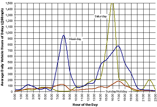
Many agencies use a freeway lane capacity 2,200 vehicles per hour per lane (vphpl). 2,000 or 2,200 vphpl are commonly used by engineers as the design capacity, or the bottleneck capacity of an urban freeway lane. Figure 3.2 shows an example summary of average daily delay on a hypothetical corridor.
For arterials and surface streets a similar threshold is needed to separate congested speed from free flow – the speed limit or the 85th percentile travel speed can be used to make the calculation applicable to arterials and surface streets.
Figure 3.2 Example Average Daily Delay by Day of Week and Time of Day
VMT, PMT and RPMT, VHT and VMT, and PHD
Vehicle and person-miles or hours traveled (VMT and PMT) and person hours of delay (PHD) are relatively straightforward calculations once travel times and delays are established. VMT is computed by segment by time period as the flow × the segment length. Along a corridor, multiple segment VMT can be summed to arrive at the corridor-level VMT. PMT is simply VMT × average vehicle occupancy. Where transit ridership and vehicle occupancy data are available, PMT can be calculated for a segment by multiplying ridership by distance. In this case, total PMT is:
(Total Autos) × (Segment Length) × (Average Auto Occupancy) + (Total Transit Ridership) × (Segment Length)
If specific transit ridership is not available, PMT can be computed as:
(Total VMT) × (Average Vehicle Occupancy)
As with VMT, PMT can be aggregated from the segment level to the corridor level. It is advised to use household survey vehicle occupancy data with caution, since it is based on a sample size that may not be factored appropriately for corridor-level analyses.
PHD is computed by multiplying vehicle hours of delay times average auto occupancy. Autos should be computed as total vehicles less transit vehicles, if possible. For transit, estimate total transit ridership during the peak period and multiply it by delay per transit vehicle hours of delay, where applicable (i.e., distinguish between HOV and mainline speeds to use for transit travel times). If transit-specific data is not available, multiply vehicle hours of delay by average vehicle occupancy gathered from other sources.
A multimodal performance measure that can useful in ICM AMS is “Reliable PMT” (RPMT) – this measure can help summarize transit, arterial, and freeway performance into one measure that describes corridor performance. The “Reliable” part of RPMT can be derived by comparing the PMT for a certain scenario to a target maximum or optimal RPMT (RPMT*). This can be calculated analytically by loading a simulation network incrementally to some maximum throughput level before systemwide decline. An acceptable RPMT could then be defined as an RPMT that does not deviate more than x percent from RPMT*. RPMT is not an observable field measure; however, high RPMT is likely associated with values of observable field measures like travel time, travel time reliability, and bottleneck throughput.
Reliability
Reliability captures the relative predictability of the public’s travel time. Unlike mobility, which measures how many people are moving at what rate, the reliability measure focuses on how much mobility varies from day to day. Analysis techniques that can be used to forecast travel time reliability include the use of simulation models (e.g., performing multiple runs of the same forecast scenario, while adjusting flows and/or other input variables); or the ITS Deployment Analysis System (IDAS) methodology; or the Highway Economic Requirements System (HERS) methodology; or the TTI “buffer index” method.
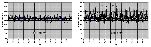
To illustrate the importance of the reliability measures, Figure 3.3 shows two hypothetical corridors of the same length having the same average weekday travel time of around 22 minutes (i.e., they have the same level of mobility). However, Corridor “B” on the right side of the figure has a much wider day-to-day variation in travel time, and is less reliable than corridor “A.” Even though they both experience the same average level of mobility, it is very likely that the travelers on Corridor “B” will remember those days where the travel time exceeded 35 minutes much more than the travelers on Corridor “A” will remember those few days where their travel time barely exceeded 25 minutes.
The “buffer index” method can be used to estimate reliability in conjunction with other measures, such as the standard deviation of travel time or using other percentile measures (e.g., the 85th percentile travel time). The buffer index is defined as the extra time (or time cushion) that travelers must add to their average travel time when planning trips to ensure on-time arrival. On-time arrival assumes the 95th percentile of travel time distribution.Figure 3.3 Illustrative Difference Between Mobility and Reliability
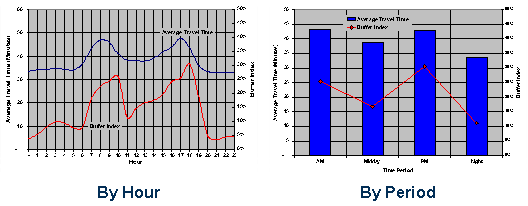
The buffer index is fairly easy to communicate to the general public. It also is presented as a percentage, which makes it comparable among the different corridors and modes. Figure 3.4 illustrates two ways to present the buffer index. The first chart in the figure shows the average travel time and the buffer index by hour of the day. The second chart on the right averages the travel time over the four periods of the day (a.m., p.m., midday, and evening/early morning).
Figure 3.4 Different Ways to Present the Buffer Index
For example, a buffer index of 30 percent for a corridor of 10 miles has the same relative reliability as a 30 percent buffer index for a corridor of 20 miles. The FHWA has a web site with more detailed information on how to apply the buffer index for planning purposes and provides links to additional resources at http://ops.fhwa.dot.gov/publications/tt_reliability/.
To illustrate, a buffer index of 40 percent means that, for a trip that usually takes 20 minutes, a traveler should budget an additional 8 minutes to ensure on-time arrival most of the time:
Average travel time = 20 minutes
Buffer index = 40 percent
Buffer time = 20 minutes × 0.40 = 8 minutes
The average travel time can be estimated as described above in the travel time calculation discussion from above. The 95th percentile travel time can be obtained by sorting each day’s travel time for the given hour. The buffer index is the difference between the 95th percentile travel time and the average travel time for the year divided by the average travel time:
![]()
Safety
For the safety performance measure, it is suggested to use the number of accidents and accident rates from accident databases linked to highway databases. The highway database contains description elements of highway segments, intersections and ramps, access control, traffic volumes and other data. Accident databases contain specific data for accidents on state highways. Each accident record contains a ramp, intersection, or highway post mile; and includes other data, such as the following:
- Location;
- Time and date;
- Severity;
- Primary collision factor;
- Environmental information (e.g., weather);
- Roadway conditions;
- Type of collision;
- Number of vehicles involved;
- Party type;
- Condition of party;
- Actions of party; and
- Casualties per party.
3.3 Analysis of Non-Recurrent Congestion
Collectively, all the tools in the ICM AMS framework are capable of supporting the analysis of both recurrent and non-recurrent corridor scenarios. The non-recurrent scenarios that will be supported include major and minor incidents (unplanned), special events, weather, and work zones. These non-recurring scenarios entail various combinations of increases of demand and decreases of capacity. The relative frequency of non-recurrent conditions is also important to estimate in this process – based on archived traffic conditions. Otherwise, resource allocation may be drawn towards highly unlikely events.
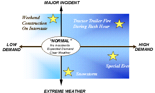
Figure 3.5 depicts this approach: key ICM impacts may be lost if only “normal” travel conditions are considered; the proposed scenarios take into account high and low travel demand, incidents, work zones, and weather conditions. These are sources of variation in the performance of the transportation system. Possible analysis scenarios are depicted in Figure 3.6.
Figure 3.5 Key ITS Impacts May Be Lost If Only “Normal” Conditions Considered
Source: Wunderlich, K., et al., Seattle 2020 Case Study, PRUEVIIN Methodology, Mitretek Systems. This document is available at the FHWA Electronic Data Library (http://www.itsdocs.fhwa.dot.gov/).
Figure 3.6 Sources of System Variation: Classifying Frequency and Intensity
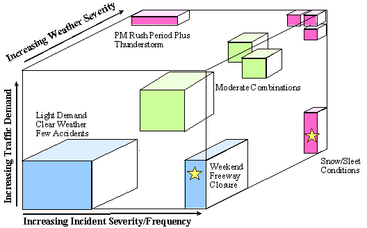
Source: Wunderlich, K., et al., Seattle 2020 Case Study, PRUEVIIN Methodology, Mitretek Systems. This document is available at the FHWA Electronic Data Library (http://www.itsdocs.fhwa.dot.gov/).
3.4 Analysis Approach – Existing Conditions
This section outlines the general approach for evaluating existing conditions. There are “rules of thumb” that should be applied where possible:
- Use available collected data or field observations to characterize existing traffic conditions; and
- Define the study area and analysis timeframe so as to contain traffic congestion.
The timeframe for analysis should focus on weekday peak-period conditions. Weekends should be assessed where such an analysis would influence projects or strategies to be used, or where weekend conditions vary considerably from the weekday.
Peak-period analyses should be performed at a minimum, and hourly estimates should also be used where appropriate data are available. Mid-day and off-peak periods would be of interest, if data are readily available. If after an assessment of the availability of existing traffic data the study teams determine that data gaps exist, the analysis teams should make a recommendation for additional data collection.
In addition to corridor-wide performance for existing conditions, individual bottlenecks should be evaluated to determine their overall contribution to corridor congestion. Once bottlenecks are identified field observations need to be performed to determine and document the cause of the bottlenecks.
Existing and future corridor conditions should also be assessed for arterials in addition to freeways. Mean speeds and average traffic volumes can be used to describe arterial traffic performance, for both the baseline and mitigation strategies.
3.5 Analysis Approach – Future Conditions
Two analysis levels are recommended for the analysis:
- First, in comparing alternatives, a low-level/screening analysis should be used to screen out non-viable alternatives; and
- Second, viable alternatives that emerge from the screening analysis should be assessed using higher-level, more detailed analysis.
Analysis Timeframe
In conducting the analysis, the study area and analysis timeframe should be defined so as to contain congestion both spatially and temporally. The primary focus in ICM AMS traffic analyses is on peak weekday periods – not only peak-hour conditions. Weekends should be assessed where the analysis would potentially influence the selection of projects or strategies.
If assumptions need to be made for peak spreading in future traffic conditions, the analyst can check the reasonableness of future queues and travel demand, and make peak-spreading assumptions that would result in queues and delays that would be acceptable by the traveling public. The peak-spreading approach should be thoroughly documented and applied to both future baseline and alternatives so that benefits of the improvements can be demonstrated in a consistent way across alternatives.
Analysis of ICM Strategies
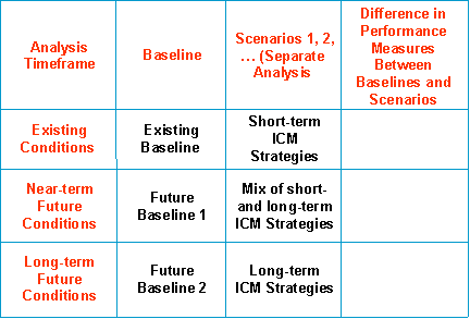
The identified ICM strategies will be segregated into short- and long-term implementation timelines. The identified strategies should then be grouped into analysis scenarios. Figure 3.7 shows the desired organization of analysis scenarios and results.
- At the start of the corridor analysis, an Existing Conditions Baseline will be established and calibrated to replicate observed traffic performance;
- Using travel demand model forecasts and model calibration characteristics identified in the Existing Conditions Baseline, future baselines will be established, including Future Baseline 1 (for a near-term future year) and Future Baseline 2 (for a longer-term future year);
- For each of the analysis, horizons analysis scenarios will be developed using short- and long-term ICM strategies; and
- For each scenario and for each performance measure, analysis results will be report absolute values and differences between each scenario and its corresponding baseline.
Figure 3.7 Example Analysis Scenarios
Cost Estimation
For the identified mitigation strategies, the analysis team should prepare planning-level cost estimates, including life-cycle costs (capital, operating, and maintenance costs). Costs should be expressed in terms of the net present value of various components. The analysis team can use consistent percentages for soft costs, such as design and contingency costs. Also, the FHWA Cost Database can be used to assist in producing capital and operating and maintenance (O&M) costs for ICM strategies.
3.6 Output
The output of each ICM corridor analysis should be a well written narrative of the identified problems and recommended solutions, and a clear and concise description of an implementation sequence and schedule for project and strategies for any given corridor. In addition to the narrative, output and reports should be graphical to the extent possible, and then tabular. Output performance measures must be consistent across corridor analyses, existing and future conditions, and mitigation strategies and scenarios.
Each corridor report should include the following chapters:
- Corridor description – A description of the corridor roadway and transit network, including a map showing the corridor study network and a detailed description of existing traffic performance on the corridor with specific explanations of the causes of congestion problems.
- Analysis methodology – A description of performance measures and methodology employed for corridor analysis, including assumptions, data and tools/models used, and model calibration characteristics.
- Existing conditions – Analysis results for existing conditions, including causes of existing recurrent and non-recurrent traffic congestion problems in the corridor, locations of freeway bottlenecks, and other locations that may constitute mobility constraints in the corridor, such as freeway ramps or arterial intersections.
- ICM strategies – A description of viable short- and long-term ICM strategies for the corridor.
- Future conditions – Analysis results for future conditions, including causes of future recurrent and non-recurrent traffic congestion problems in the corridor, changes in aggregate congestion levels in the corridor, changes in peak-period travel times and delays, and locations of freeway bottlenecks. For all identified mitigation strategies, analysis results for all performance measures and planning-level cost estimates.
- Cost-benefit analysis – A prioritization effort based on cost-benefit analysis providing a basic comparison of cost-effectiveness across all identified ICM strategies and projects. This analysis will estimate the economic value of project impacts, benefits, and costs in a consistent analysis framework. A possible method to be employed in this analysis includes IDAS.
- Recommendations – A prioritized list of recommended ICM strategies, including a narrative explaining the rationale for the prioritization. A summary of results of the traffic operations analysis and a prioritized list of congestion relief measures, including recommendations for any modifications to proposed projects and strategies.